
DistributionSolar
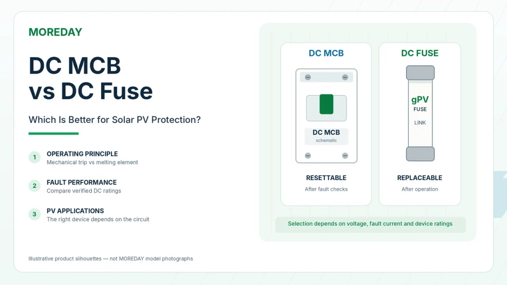
The main difference between a DC MCB and a DC fuse is how they interrupt overcurrent and how they are restored after operation. A DC miniature circuit breaker uses a mechanical contact system and protective trip mechanism, allowing it to be reset after a fault has been cleared and the device has been checked. A DC fuse interrupts current by melting its internal element and must be replaced after operation.
For solar photovoltaic systems, neither device is universally better. A properly selected gPV fuse can provide protection against the relatively low overcurrents associated with certain PV faults, while an appropriately rated DC circuit breaker offers resettable protection and, where specifically approved, switching or isolation capabilities.
The correct choice depends on the available fault current, maximum DC voltage, time-current characteristics, breaking capacity, applicable standards, and the equipment being protected.
This guide compares DC MCBs and DC fuses and explains how to select the appropriate solution for PV strings, combiner boxes, and other DC applications.
How Do DC MCBs and DC Fuses Work?
Both devices provide overcurrent protection, but their operating mechanisms are different.
How a DC Miniature Circuit Breaker Works
A DC MCB is a mechanical circuit breaker designed to open its contacts when specified overcurrent conditions occur.
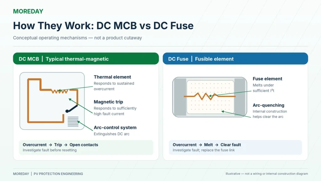
Many conventional DC MCBs use thermal-magnetic protection:
- Thermal protection: A bimetallic element responds to sustained overcurrent.
- Magnetic protection: An electromagnetic mechanism responds to sufficiently high fault current.
- Arc-extinguishing system: Helps interrupt the DC arc after the contacts separate.
When a DC MCB trips, the contacts open and interrupt the circuit within the device’s rated capabilities.
The breaker can generally be reset after the fault has been investigated and cleared, provided that it remains serviceable and the manufacturer’s instructions permit re-energization.
However, a circuit breaker is not designed for unlimited fault interruptions or unlimited switching cycles.
Its mechanical endurance, electrical endurance, and post-fault serviceability must be considered.
How a DC Fuse Works
A DC fuse contains a calibrated fusible element.
When sufficient overcurrent flows for a specified duration, the element heats and melts, initiating the interruption process.
The typical operating sequence is:
Overcurrent → Fuse element heating → Element melting → Arc formation → Arc extinction → Circuit interruption
The fuse cannot be reset.
After operation, the fault must be investigated and the operated fuse link replaced with an appropriate equivalent.
Unlike a mechanical circuit breaker, the fuse has no resettable contact mechanism.
Why DC Arc Interruption Matters
Direct current does not have the periodic natural current-zero crossings found in AC systems.
Therefore, both DC MCBs and DC fuses must be capable of extinguishing an electrical arc at their rated DC voltage and specified fault-current conditions.
A circuit breaker typically uses a contact and arc-control system.
A high-breaking-capacity fuse uses its specially designed element and internal arc-extinguishing arrangement.
Neither construction guarantees suitable performance unless the product has appropriate DC ratings.
For a detailed introduction to fuse operation, see What Is a DC Fuse?.
DC MCB vs DC Fuse: Key Differences
The following table summarizes the practical differences between these two protective devices.
| Feature | DC MCB | DC Fuse |
|---|---|---|
| Operating mechanism | Mechanical contacts and trip system | Fusible element melts |
| Resettable | Generally yes, after fault investigation | No, replacement required |
| Time-current characteristic | Determined by trip unit and breaker design | Determined by fuse-link design |
| Breaking capacity | Model- and voltage-dependent | Model- and voltage-dependent |
| Current-limiting performance | Available in certain designs | Available in suitable fuse designs |
| Manual switching | Permitted within specified switching ratings | Fuse link is not a switch |
| Isolation | Only if suitably rated and approved | Requires a suitable separate isolating arrangement |
| Maintenance after operation | Investigate fault and assess breaker condition | Investigate fault and replace fuse link |
| PV string protection | Requires suitable PV-specific ratings and characteristics | gPV fuse links are designed for PV protection |
| Physical installation | DIN rail or other specified mounting | Compatible fuse holder or mounting arrangement |
| Cost considerations | Often higher initial component cost | Often lower fuse-link cost, with replacement expense |
Which Device Has a Higher Breaking Capacity?
Neither type has a universal breaking-capacity advantage.
Some high-breaking-capacity DC fuse links can interrupt fault currents significantly higher than those handled by certain compact DC MCBs.
However, this does not mean that all fuses have higher breaking capacities than all circuit breakers.
Industrial DC circuit breakers, including appropriately rated molded-case devices, may also provide substantial short-circuit interruption capabilities.
The comparison must use the actual ratings at the required DC voltage and specified circuit conditions.
For breakers, relevant IEC 60947-2 parameters include the rated ultimate short-circuit breaking capacity (Icu) and rated service short-circuit breaking capacity (Ics), where applicable.
For fuses, engineers should review the rated breaking capacity and the specified fuse operating characteristics.
Which Device Is Easier to Maintain?
A resettable circuit breaker can reduce the need to stock and replace fuse links.
However, resetting a breaker does not repair the underlying electrical fault.
A device that trips repeatedly requires investigation, and a breaker subjected to a severe interruption may need inspection or replacement according to its manufacturer’s guidance.
A fuse requires physical replacement after operation, but its relatively simple construction can be advantageous in applications where suitable fuse performance is available.
The total maintenance cost depends on the application, accessibility, fault frequency, spare-part availability, and inspection requirements.
Is a DC MCB Also an Isolator?
Not automatically.
Some circuit breakers are specifically rated and marked as suitable for isolation.
Others may provide overcurrent protection without satisfying all requirements for a particular isolation or load-switching application.
A DC MCB should be used for isolation or manual switching only when its technical documentation, ratings, and applicable standards permit that function.
A normal fuse link is not a load-break switch. A fuse holder must not be opened under load unless the complete assembly is specifically rated for the intended operation.
Trip Curves, Clearing Time and Breaking Capacity
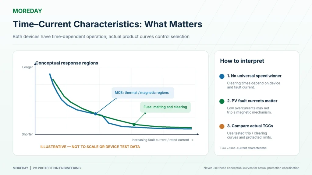
Response time is one of the most misunderstood differences between DC MCBs and DC fuses.
A statement such as “a fuse always operates in less than 5 milliseconds” or “an MCB always takes 20–100 milliseconds” is technically unreliable.
Actual interruption time depends on fault-current magnitude, device construction, operating characteristics, and test conditions.
DC MCB Thermal and Magnetic Tripping
A thermal-magnetic DC MCB has different operating behavior at different overcurrent levels.
At moderate overload currents, the thermal mechanism may require a relatively long time to operate.
At sufficiently high fault currents, the magnetic mechanism may trip much more quickly.
The operating thresholds must be verified from the manufacturer’s published characteristics.
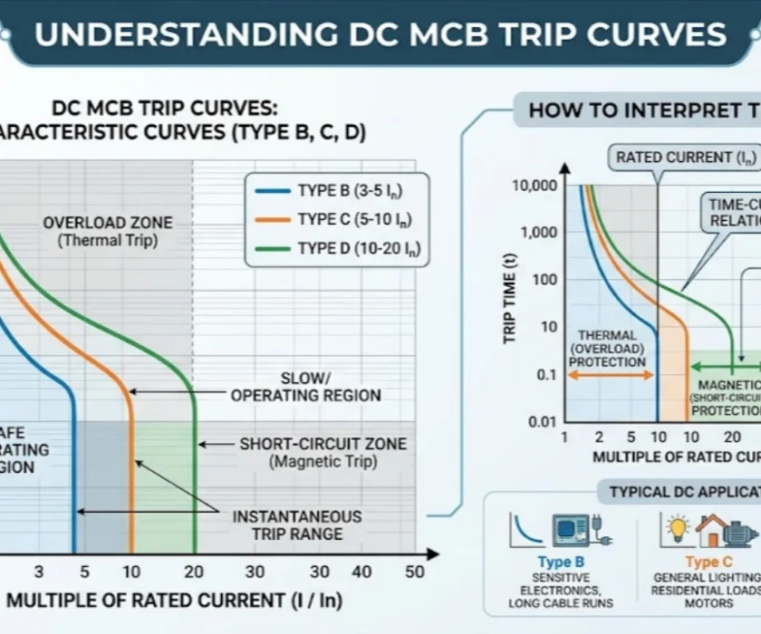
Common B and C trip curves are associated with different instantaneous trip-current ranges, but their suitability for DC applications must be established using the actual DC product data.
The trip behavior of a DC breaker should not be determined solely from a generic AC trip-curve diagram.
For further explanation, see DC MCB Trip Curves: B, C and D.
DC Fuse Time-Current Characteristics
A fuse also has a time-current characteristic.
At a relatively low overcurrent, it may take a considerable time to operate.
At higher fault currents, the element may melt and interrupt the circuit much faster.
For photovoltaic applications, gPV fuses are designed for the particular overcurrent characteristics of PV strings and arrays.
These devices must not be confused with high-speed semiconductor fuses, such as appropriate aR or gR types.
A gPV fuse is not automatically suitable for semiconductor protection merely because it is a fuse.
For additional technical details, read What Is a gPV Fuse?.
Understanding I²t and Let-Through Energy
I²t is an important characteristic in fuse protection and electrical coordination.
It is expressed as:
I²t = ∫ i²(t) dt
It represents the time integral of the square of current.
For fuses, engineers may distinguish between:
- Pre-arcing I²t: Associated with the current flowing before the fuse element melts.
- Total clearing I²t: Associated with the complete interruption process.
I²t is useful for assessing thermal stress and protective-device coordination.
However, it should not be described as the exact energy delivered to every protected component. Actual energy dissipation also depends on the circuit and equipment characteristics.
A semiconductor’s protection requirements, for example, may involve additional considerations beyond a simple comparison of two I²t values.
Why PV Fault Current Requires Special Attention
Solar PV modules are current-limited sources.
In many PV circuits, the available short-circuit current is only moderately higher than the normal operating current.
This can make it difficult for an unsuitable protective device to operate quickly enough under certain faults.
Consider a simplified four-string PV array:
| Parameter | Example |
|---|---|
| String short-circuit current | 13A |
| Parallel strings | 4 |
| Module maximum series fuse rating | 25A |
| Estimated current from three healthy strings | 39A |
The simplified reverse-current contribution is:
Ireverse ≈ (4 − 1) × 13A = 39A
A protective device rated at 25A cannot be assumed to interrupt this current within an acceptable time merely because 39A exceeds 25A.
The ratio is only:
39A / 25A = 1.56 × rated current
At this level, the time-current characteristics of the proposed MCB or fuse become particularly important.
A conventional breaker may not reach its magnetic trip threshold, while a gPV fuse must also be checked against its relevant operating requirements and the withstand limits of the protected equipment.
This example is illustrative and does not replace the applicable fault-current calculations or protection coordination assessment.
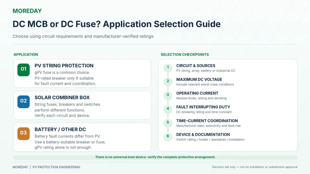
DC MCB vs DC Fuse for Solar PV Strings and Combiner Boxes
Solar photovoltaic applications are one of the most important areas where the choice between DC MCBs and fuses requires careful engineering evaluation.
PV String Protection
When multiple PV strings are connected in parallel, a faulted string may receive current contributions from the other strings.
If the available fault current can exceed the relevant module, conductor, or equipment limits, appropriate overcurrent protection may be required.
A properly selected gPV fuse is a common solution for PV string overcurrent protection.
A suitable PV-rated circuit breaker may also be an option, provided its operating characteristics and interruption capabilities meet the protection requirements.
It is incorrect to assume that a resettable DC MCB is always the preferred device for solar string protection.
The protective device must work under the actual PV fault-current conditions.
For an explanation of when string protection is required, see PV String Fuse Requirements.
Solar Combiner Box Protection
A solar combiner box may contain:
- Individual string fuse links and holders.
- Appropriately rated DC circuit breakers.
- DC switching or isolating devices.
- Surge protective devices.
- Collection busbars and output terminals.
These components perform different electrical functions.
A gPV string fuse may protect an individual PV source circuit from qualifying reverse-current faults.
A DC breaker may protect another specified circuit, such as an array output, when the device is appropriate for the available current and fault conditions.
A suitably rated switch-disconnector may provide the required operational switching or isolation function.
The correct arrangement depends on the complete combiner box design.
For more information, see How to Select Fuses for Solar Combiner Boxes.
Does Every Solar String Need an MCB or Fuse?
No.
Some PV string configurations may not require individual overcurrent protection when the conductors and equipment are adequately rated and the applicable design rules permit omission.
Other configurations require overcurrent protection because of parallel string backfeed or additional fault-current sources.
Protection requirements must be established before deciding whether a fuse or breaker is appropriate.
What About 1000V and 1500V PV Systems?
Both DC MCBs and fuse links must have suitable ratings for the maximum voltage they may be required to interrupt.
A 1000V marking does not automatically establish suitability for every nominally 1000V system, and a 1500V marking does not automatically guarantee compatibility with all lower-voltage applications.
For DC breakers, the number of poles, series-pole arrangement, wiring direction, and polarity restrictions may also affect the permitted voltage rating.
For example, some high-voltage DC breaker configurations require multiple poles connected in series according to a specific manufacturer wiring diagram.
A four-pole breaker must not be assumed to have the same voltage capability under every possible connection arrangement.
See 1000V vs 1500V DC Fuses for the related voltage-selection considerations.
Which Device Is Suitable for Battery and Other DC Applications?
The answer can change significantly outside solar PV string circuits.
Battery systems, industrial DC distribution, and power-conversion equipment may have different fault-current characteristics.
Battery Energy Storage Systems
Battery circuits can produce high prospective short-circuit currents because of the characteristics of the battery and its electrical connections.
The fault current can be substantially different from the limited short-circuit current of a conventional PV string.
The protective device must therefore be evaluated for:
- Maximum battery system voltage.
- Prospective short-circuit current.
- DC circuit time constant.
- Continuous operating current.
- Required interruption performance.
- Equipment protection coordination.
- Applicable battery-system requirements.
A gPV fuse should not automatically be specified for a battery circuit.
Likewise, a DC MCB advertised for solar applications should not automatically be treated as suitable for battery protection.
The exact product must be evaluated for the battery application.
Power Semiconductor Protection
Power converters and inverters may contain IGBTs, MOSFETs, and other semiconductor devices.
Certain semiconductor applications require extremely low let-through energy or carefully controlled fault interruption.
Specialized semiconductor fuses may be selected for these applications.
However, fuse suitability must be verified against the semiconductor’s actual protection requirements and the manufacturer’s coordination guidance.
A DC MCB may protect an upstream circuit without providing the specialized protection required by an individual semiconductor component.
Similarly, a gPV fuse should not be confused with a dedicated semiconductor fuse.
Industrial DC Distribution
In industrial DC distribution, a properly selected circuit breaker can provide resettable overcurrent protection and possibly operational switching functions.
Fuses may be appropriate where their current-limiting behavior, breaking capacity, equipment coordination, or installation requirements favor their use.
Selection should be based on the circuit’s actual operating conditions rather than a universal preference for one protective technology.
Can a DC MCB and DC Fuse Be Used Together?
Yes. A DC circuit breaker and a fuse may be incorporated into the same protection system when the arrangement is appropriately designed and verified.
However, using both devices does not automatically produce better protection.
Series Protection and Coordination
A fuse may be used with a breaker where the design requires coordinated short-circuit protection.
For example, the combination may be intended to:
- Protect specific circuits against different fault conditions.
- Provide backup or cascading protection where permitted.
- Limit the energy or current reaching downstream equipment.
- Improve discrimination or selectivity under defined conditions.
These outcomes require coordination analysis.
For example, installing a fuse upstream of a breaker does not guarantee that the breaker will always trip first.
At different fault-current levels, the devices may have different operating sequences.
Engineers should evaluate the manufacturer’s time-current curves, interruption data, and tested coordination information.
Selectivity vs Backup Protection
Selectivity aims to isolate the affected part of a system while minimizing unnecessary disconnection elsewhere.
Backup protection, sometimes called cascading, may allow a coordinated upstream device to assist another protective device under specified fault conditions.
These are not the same design objective.
A backup arrangement must not be assumed acceptable based only on the rated currents of the two devices.
Where relevant, the combination must be supported by appropriate manufacturer documentation and applicable standards.
Practical Selection Checklist
The following checklist can be used to compare candidate devices.
| Selection Item | Engineering Requirement |
|---|---|
| Protection objective | Identify the circuit and equipment to be protected |
| Circuit type | Confirm PV string, array output, battery, or industrial DC application |
| Maximum voltage | Calculate the highest relevant DC voltage |
| Operating current | Determine continuous current and applicable derating |
| Available fault current | Evaluate all relevant sources |
| Breaking capacity | Check tested ratings at the required DC voltage |
| Operating characteristic | Compare time-current curves and protected-equipment limits |
| Isolation and switching | Determine whether separate rated switching equipment is required |
| Coordination | Verify performance with other protective devices |
| Installation conditions | Check temperature, mounting, wiring and enclosure |
| Compliance | Confirm applicable standards and exact product documentation |
The correct decision depends on whether the proposed device can protect the actual circuit under the required operating and fault conditions.
Applicable Standards and MOREDAY DC Protection Solutions
Different product standards apply to DC circuit breakers and photovoltaic fuse links.
IEC and UL Standards
| Standard | Application |
|---|---|
| IEC 60947-2:2024 | Low-voltage circuit breakers within its specified scope |
| IEC 60269-6:2010+A1:2021 | Photovoltaic fuse links |
| IEC 62548-1:2023+A1:2025 | PV array design and electrical protection |
| UL 489B | Molded-case circuit breakers and related equipment for PV applications |
| UL 248-19 | Photovoltaic fuse product requirements |
IEC 60947-2:2024 covers circuit breakers within its specified voltage and application limits.
IEC 60269-6 establishes supplementary requirements for photovoltaic fuse links.
These are product standards, whereas IEC 62548-1 addresses PV array design requirements.
For North American projects, the applicable listing and installation rules must be checked for the actual device.
In particular, a supplementary protector evaluated under UL 1077 should not automatically be substituted for a branch-circuit protective device requiring a different listing.
A product’s IEC standard reference does not independently establish UL certification or listing.
MOREDAY DC MCB Product Range
MOREDAY offers several DC miniature circuit breaker families for photovoltaic and industrial DC applications.
The MOREDAY DC Circuit Breaker Range includes the MDB1Z-63 series and other configurations with different pole arrangements, current ratings, and DC voltage capabilities.
For example, the MDB1Z-63 DC Miniature Circuit Breaker is offered in several pole configurations for DC protection applications.
When selecting a particular reference, verify the actual rated DC voltage, breaking capacity, trip characteristics, permitted wiring arrangement, and applicable documentation.
MOREDAY DC Fuse Solutions
MOREDAY also provides photovoltaic fuse links and fuse holders.
The DC Fuse Product Range includes product families for 1000V and 1500V PV applications.
The 1000V/1500V DC Fuse Link product family provides different cylindrical fuse configurations.
The final selection should use the precise fuse model, verified gPV characteristics where required, breaking capacity, and compatible holder.
The availability of both DC MCBs and fuses allows engineers to evaluate different protection architectures without assuming that either device is universally superior.
Requesting a Technical Recommendation
For EPC contractors, equipment manufacturers, and distributors, MOREDAY can assist with identifying candidate protective devices based on the project requirements.
Useful information includes:
Application → Maximum DC voltage → Rated current → Available fault current → Protection objective → Required standards → Mounting configuration → Technical documentation
For combiner box projects, the PV module specifications, string configuration, and required switching arrangement should also be provided.
Conclusion
Choosing between a DC MCB and a DC fuse requires an assessment of the circuit’s protection requirements rather than a simple comparison of reset capability or component price.
A DC MCB offers resettable overcurrent protection and may provide additional switching or isolation functions when suitably rated.
A DC fuse provides protection through a calibrated fusible element and may offer advantageous current-limiting and interruption characteristics in suitable applications.
For photovoltaic strings, a correctly specified gPV fuse or an appropriately rated PV circuit breaker must be selected according to the actual fault-current conditions.
Neither device can be assumed to replace the other solely because its rated current and voltage appear similar.
Explore MOREDAY DC Circuit Breakers and MOREDAY DC Fuses to compare available solutions and request model-specific technical information.