

Energy StorageSolar
A DC fuse is an overcurrent protection device designed to interrupt direct current when a fault produces sufficient current to melt its internal fuse element. Unlike an ordinary switch, a fuse operates automatically according to its time-current characteristics and must be replaced after it has operated.
DC fuses are widely used in photovoltaic (PV) systems, DC distribution equipment, and other applications requiring protection against excessive current. In solar installations, specially designed gPV fuse links help protect PV strings and associated wiring against potentially damaging reverse currents and other fault conditions.
Understanding how DC fuses operate, what their ratings mean, and where they should be installed is essential for selecting reliable electrical protection.
This guide explains the key principles and provides a practical selection framework for solar PV applications.
What Is a DC Fuse?
A DC fuse is a protective component containing a calibrated metal element that melts when the current and operating duration exceed its designed limits.
In a healthy circuit, the fuse carries the normal operating current. During a qualifying overload or short-circuit fault, heat generated inside the element causes it to melt, opening the circuit.
The fuse’s purpose is to limit the duration and consequences of excessive current. It is not designed to regulate voltage, detect every electrical fault, or replace the need for appropriate isolation and other protective devices.
DC Fuse Link vs Fuse Holder
Although these terms are sometimes used interchangeably, they describe different components.
| Component | Primary Function | Important Consideration |
|---|---|---|
| DC fuse link | Contains the fusible element that interrupts overcurrent | Must have suitable current, voltage, and breaking ratings |
| DC fuse holder | Supports the fuse link and provides electrical connections | Must be compatible with the fuse link and installation conditions |
| Fuse assembly | Combines a fuse link with compatible mounting or holding equipment | Its performance depends on the correctly matched components |
The fuse link performs the actual current interruption. The holder provides the mounting and connection interface.
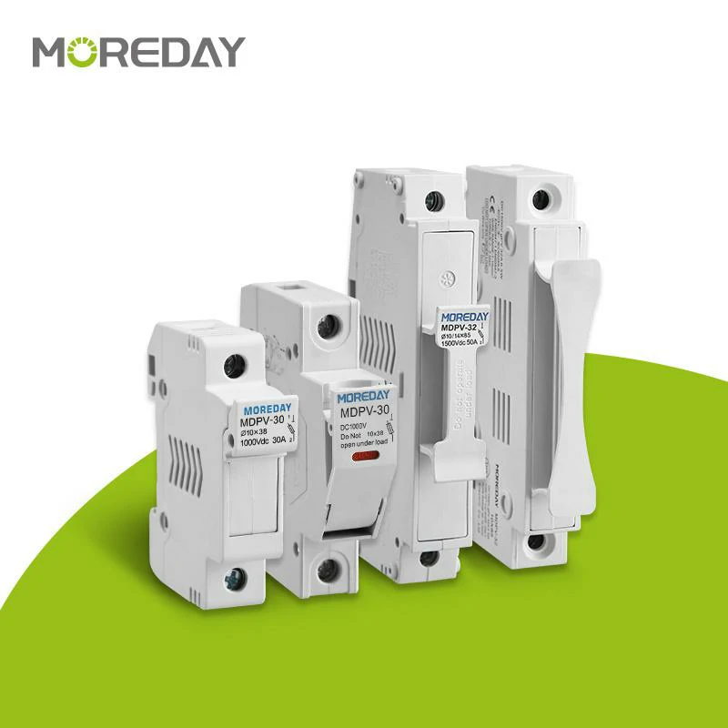
For example, MOREDAY offers DC fuse links for 1000V and 1500V applications alongside compatible product families such as the MDPV-30 1000V DC fuse holder.
For a closer explanation of the mounting component, see What Is a Fuse Holder and How Does It Work?.
How Does a DC Fuse Work?
A DC fuse operates through thermal and electrical processes that take place inside its fuse element.
The basic sequence is:
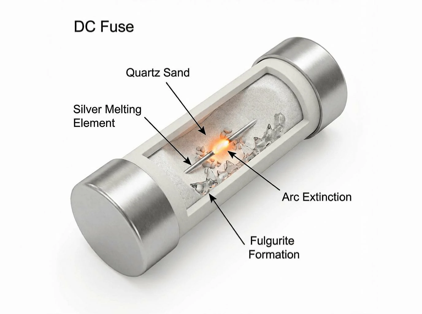
Normal current flow → Excessive current → Element heating → Element melting → Arc formation → Arc extinction → Circuit interruption
Current Flow and Element Heating
Under normal conditions, current passes through the fuse element without causing it to melt.
Every fuse element has electrical resistance. As current flows through it, heat is generated. A properly selected fuse is designed to carry its specified operating current under the applicable installation and temperature conditions.
When current increases, the rate of heat generation rises. If the excessive current persists long enough, the element reaches its melting point.
The operating time depends on the current magnitude and the fuse’s time-current characteristic. A fuse rated at 20A, for example, does not necessarily open immediately when the current reaches 20.1A.
Why Interrupting DC Is Challenging
An important difference between AC and DC protection involves electrical arcing.
Alternating current passes through zero periodically. This natural current-zero condition can assist arc extinction.
Direct current does not have the same periodic zero crossing. When a DC fuse element melts, an electrical arc may form between the separated portions of the element. The fuse must extinguish that arc and withstand the resulting recovery voltage.
Many industrial high-breaking-capacity fuse links employ arc-quenching materials, such as quartz sand, together with carefully designed internal elements to control the interruption process.
Consequently, a fuse’s AC voltage rating must not be assumed to establish its suitability for DC service.
A product should be used in a DC circuit only when its manufacturer specifies appropriate DC ratings for the intended conditions.
For additional technical differences, read DC Fuse vs AC Fuse: Key Differences and Applications.
Understanding Time-Current Characteristics
A fuse does not have one fixed operating time.
Its response depends on the relationship between current magnitude and duration:
- At normal operating current, the fuse should remain intact under its specified conditions.
- At a sustained overcurrent, the fuse may eventually operate according to its time-current curve.
- At sufficiently high fault current, interruption generally occurs much faster.
In PV systems, this characteristic is particularly important because solar modules are current-limited sources. Certain PV faults can produce relatively low overcurrents compared with faults supplied by conventional electrical distribution systems.
This is one reason that PV-specific fuse characteristics matter.
Main Types of DC Fuses
DC fuses are available with different physical constructions, operating characteristics, and application ratings.
Not every fuse marked with a DC voltage rating is suitable for every DC application.
gPV Fuses for Solar Photovoltaic Systems
The gPV utilization category identifies fuse links designed for photovoltaic protection applications under the relevant IEC requirements.
PV strings can experience reverse-current faults when other parallel-connected strings contribute current into a faulted circuit.
These fault currents may be relatively low, making the fuse’s ability to interrupt the relevant overcurrent range especially important.
IEC 60269-6 establishes supplementary requirements for fuse links used to protect photovoltaic strings and arrays.
A properly selected gPV fuse can provide overcurrent protection within its defined operating range, provided the system conditions and fuse ratings are compatible.
Other DC Fuse Categories
Other DC applications may require different fuse characteristics.
| Fuse Type | Typical Application | Selection Consideration |
|---|---|---|
| gPV fuse | Solar PV strings and arrays | PV-specific fault behavior, voltage rating and low-overcurrent interruption |
| General-purpose DC-rated fuse | Suitable DC distribution circuits | Manufacturer-defined DC operating and interruption ratings |
| High-speed fuse | Power semiconductors and converters | Semiconductor protection coordination and I²t characteristics |
| Battery application fuse | Battery circuits and DC power systems | Available battery fault current, DC ratings and relevant equipment requirements |
These categories do not imply that any one fuse can automatically replace another.
In particular, a gPV fuse intended for solar string protection should not automatically be selected for a battery circuit. Battery systems can deliver substantially different prospective short-circuit currents and require application-specific protection coordination.
Common DC Fuse Sizes
Cylindrical fuse links are available in several dimensions, including:
- 10 × 38 mm
- 10 × 65 mm
- 10 × 85 mm
- 14 × 85 mm
MOREDAY lists these dimensions within its DC fuse link product range.
However, physical size alone does not determine electrical suitability. Fuse links with similar dimensions may have different voltage ratings, current ratings, operating characteristics, and approved holders.
Understanding DC Fuse Ratings and Specifications
Selecting a DC fuse requires more than matching its ampere rating to the expected load current.
The following specifications should be reviewed together.
| Specification | What It Means | Why It Matters |
|---|---|---|
| Rated DC voltage (V DC) | Maximum specified DC voltage for the fuse under rated conditions | Determines whether the fuse can safely interrupt faults at the system voltage |
| Rated current (A) | Designated current-carrying rating of the fuse link | Must be coordinated with operating current, wiring and equipment limits |
| Rated breaking capacity (kA) | Maximum prospective current the fuse is rated to interrupt under specified conditions | Must be adequate for the available fault current |
| Utilization category | Defined fuse operating and application characteristics | Helps identify suitability for PV or other applications |
| Time-current characteristic | Relationship between fault current and operating time | Determines response to different overcurrent levels |
| I²t characteristic | Current-squared time integral associated with fuse operation | Supports protection and coordination assessment |
| Dimensions | Physical size and mounting arrangement | Determines mechanical compatibility with the holder |
Rated DC Voltage: 1000V vs 1500V
Solar PV systems commonly use equipment with rated DC voltages such as 1000V or 1500V.
The required fuse voltage rating depends on the maximum voltage that may occur across the protective device during a fault.
For PV strings, the design assessment must account for the module open-circuit voltage and its increase at low cell temperatures.
The maximum PV string voltage is not simply the system’s normal operating voltage.
A useful preliminary relationship is:
Maximum string open-circuit voltage = Number of series modules × Temperature-corrected module open-circuit voltage
The actual calculation must follow the module manufacturer’s temperature coefficients, the site’s minimum design temperature, and the applicable design standard.
A 1000V DC-rated fuse must not be used where the required DC voltage rating exceeds its capabilities.
Conversely, choosing a 1500V-rated fuse does not automatically make it interchangeable with every 1000V product. Current ratings, dimensions, time-current characteristics, and holder compatibility must also be checked.
Rated Current and Fuse Coordination
The fuse’s ampere rating must support normal operation while providing the required protection during faults.
For PV applications, engineers should review:
- Module short-circuit current (Isc)
- Maximum series fuse rating or maximum overcurrent protection rating specified by the module manufacturer
- Number and configuration of parallel strings
- Expected reverse or fault current
- Cable current-carrying capacity
- Operating temperature and applicable derating
- Fuse time-current characteristics
Selecting the next standard fuse size above the expected operating current is not, by itself, a complete design method.
Breaking Capacity
Breaking capacity describes the maximum prospective fault current that a fuse is rated to interrupt under defined conditions.
For example, a fuse with a specified DC breaking capacity of 20 kA is not automatically suitable for every DC circuit where the fault current is below 20 kA. Voltage, time constant, minimum interrupting current where relevant, and application requirements must also be satisfied.
It is equally important not to confuse the breaking capacity of a fuse link with the ratings of its holder.
Always review the technical documentation for the actual components and their approved combinations.
Where Are DC Fuses Used?
DC fuses appear in many electrical systems, but photovoltaic protection is one of their most important specialized applications.
Solar PV Strings and Arrays
In a solar array, individual PV modules are connected in series to form strings. Multiple strings may then be connected in parallel.
When a fault develops in one string, current from other connected strings may flow into the affected circuit.
If the resulting reverse current exceeds the permitted limits for the modules or conductors, appropriate overcurrent protection may be required.
PV-specific fuse links can help interrupt these fault currents and limit damage.
Not every PV string requires a dedicated fuse. The need depends on the array configuration, available fault current, equipment limitations, and applicable electrical rules.
Solar Combiner Boxes
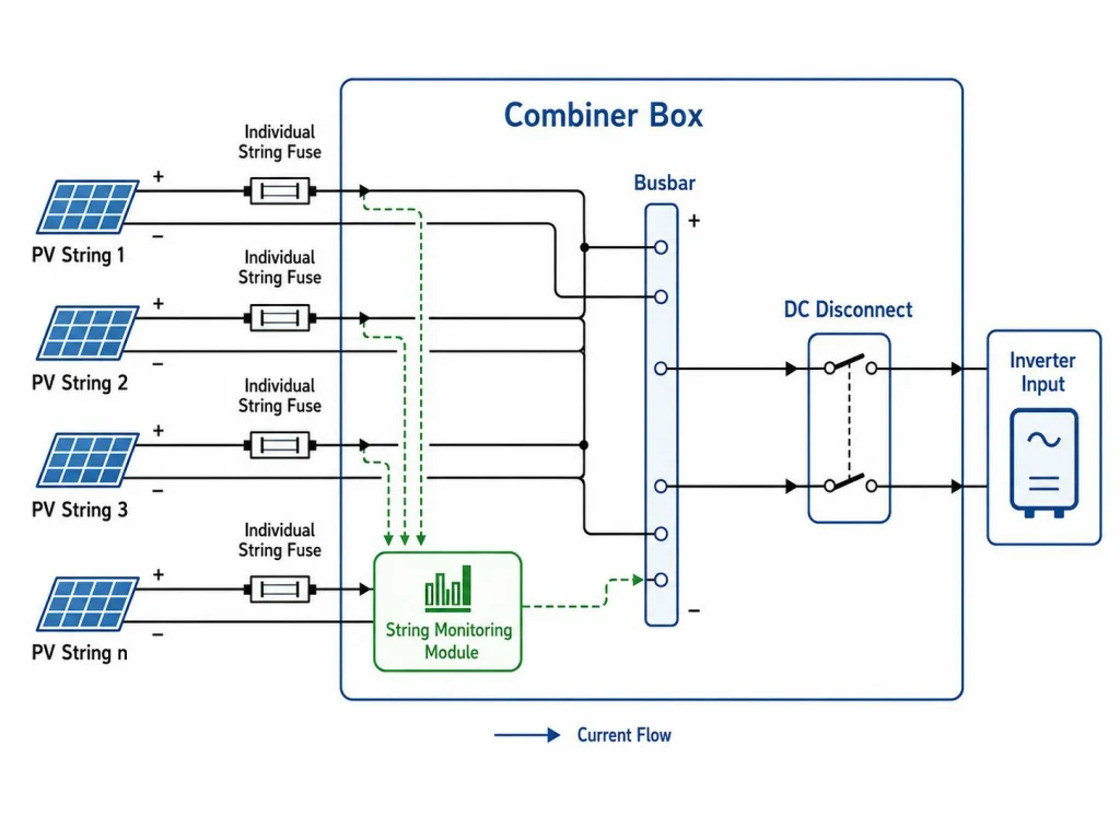
A DC combiner box brings multiple PV string circuits together into one or more output circuits.
Depending on the design, a combiner box may incorporate:
- gPV fuse links and fuse holders for string protection
- DC surge protective devices
- Suitable disconnecting or switching devices
- Terminals, conductors, and protective enclosures
Where string fuses are used, their ratings must be coordinated with the connected PV modules, conductors, and other system components.
A fuse is not a replacement for a surge protective device or a properly rated disconnecting switch. These devices perform different functions.
Inverter DC Inputs and Recombiner Equipment
Fuses may also form part of inverter input protection or larger PV array distribution arrangements.
Their placement and purpose depend on the equipment architecture.
A PV string fuse should not be assumed to protect every component inside an inverter. The inverter manufacturer may specify separate internal or external protective devices for particular fault conditions.
Battery Energy Storage and Industrial DC Systems
DC fuses are also widely used in battery energy storage systems, power conversion equipment, and industrial DC distribution.
However, battery protection is not identical to solar string protection.
A battery bank may deliver a high short-circuit current due to its relatively low internal impedance. The prospective fault current, operating voltage, circuit time constant, and protective device coordination can differ substantially from those of a PV array.
Fuses for these applications must be selected according to the battery system and equipment manufacturer’s requirements rather than chosen solely because they have a DC voltage rating.
How to Choose the Right DC Fuse for Solar PV Applications
A reliable selection process begins with the electrical design, not with an available fuse catalog.
The following checks provide a practical starting point.
Step 1: Identify the Circuit and Protection Objective
Determine whether the fuse will protect a PV string, PV array output, combiner box circuit, or another DC circuit.
Identify the equipment or conductors that require overcurrent protection and the fault conditions the device is intended to interrupt.
Step 2: Determine Whether a Fuse Is Required
Evaluate the number of parallel strings and the potential fault currents.
As an illustrative case, consider three similar PV strings connected in parallel. If a fault affects one string, the remaining strings may contribute reverse current into the faulted string.
The magnitude of this current depends on the string characteristics, irradiance, circuit configuration, and other connected sources.
Whether dedicated string fuses are required must be determined from the module’s overcurrent limits, conductor protection requirements, and the applicable design rules.
Do not rely exclusively on the number of strings.
Step 3: Calculate the Maximum DC Voltage
Calculate the maximum expected string open-circuit voltage under the site’s low-temperature conditions.
Choose a fuse link with an appropriate DC voltage rating, including any additional requirements imposed by the applicable standard or equipment manufacturer.
Step 4: Select the Fuse Current Rating
Review the module Isc, permissible module overcurrent protection rating, conductor capacity, and required design factors.
Select a fuse rating that supports continuous operation without compromising the necessary protection.
Ambient temperature and enclosure heating can influence the effective operating performance of the fuse and holder.
Use the manufacturer’s technical data and the applicable installation rules rather than applying one universal multiplier to every PV design.
Step 5: Verify the Breaking Capacity and Fuse Characteristic
Check the prospective fault current and confirm that the fuse is rated to interrupt the relevant current at the applicable DC voltage.
For conventional PV string protection, verify that the proposed fuse has the required PV protection characteristic, such as gPV where specified.
A suitable high breaking capacity alone does not prove that the device will interrupt every lower-level fault current relevant to the application.
Step 6: Match the Fuse Link and Fuse Holder
Confirm mechanical and electrical compatibility between the fuse and holder.
For example, the MOREDAY MDPV-30 is listed as a 1000V DC fuse holder designed for 10 × 38 mm fuse links.
The MOREDAY MDPV-32 is listed for 1500V DC applications and 10 × 85 mm fuse links.
These are product-family examples, not universal interchangeability rules.
Before specifying either product, verify its current rating, compatible fuse references, terminal requirements, ambient conditions, installation configuration, and relevant certification documents.
For additional holder-selection details, see How to Choose the Right DIN Rail Fuse Holder.
Step 7: Check the Complete Protection Arrangement
The final review should include fuse coordination, wiring protection, installation conditions, required isolation provisions, and equipment documentation.
For professional PV projects, document the design assumptions and the selected protective device references.
This produces a traceable engineering decision rather than a choice based only on the fuse’s printed ampere value.
DC Fuse Standards, Safety and Selection Resources
Electrical standards establish requirements for fuse performance and system design. Understanding their different scopes helps avoid incorrect product selection.
IEC 60269-6: Photovoltaic Fuse Links
IEC 60269-6 provides supplementary requirements for fuse links used to protect solar photovoltaic strings and arrays.
The consolidated edition IEC 60269-6:2010+A1:2021 addresses PV fuse links for equipment in circuits with nominal voltages up to 1500V DC.
It should be considered together with the applicable general fuse requirements, including the relevant edition of IEC 60269-1.
The standard concerns the performance requirements of PV fuse links. A product claiming compliance should be supported by the appropriate technical and conformity documentation.
IEC 62548-1: PV Array Design
IEC 62548-1 addresses photovoltaic array design requirements, including DC wiring, electrical protection, switching, and earthing provisions.
The consolidated IEC 62548-1:2023+A1:2025 edition provides an important framework for PV array protection decisions.
While IEC 60269-6 relates to PV fuse link performance, IEC 62548-1 concerns the broader design of the PV array.
Both perspectives are relevant when deciding whether protective devices are required and how they should be incorporated.
UL Requirements for North American Projects
For projects in the United States and other North American markets, designers must also consider applicable national electrical codes, product standards, and certification requirements.
UL 248-19 addresses photovoltaic fuses, while NEC Article 690 contains requirements relevant to solar photovoltaic systems.
The applicable code edition, local amendments, product listings, and equipment instructions must be confirmed for the project jurisdiction.
Compliance with an IEC standard does not automatically establish a UL listing.
Safe Installation and Replacement
A fuse link is a protective device, not a general-purpose operating switch.
Unless the complete assembly is specifically rated for the intended switching duty, a fuse holder must not be opened or operated under load.
Installation, inspection, and replacement should be carried out by qualified personnel following the relevant isolation, lockout/tagout, and verification procedures.
A fuse that has operated should not simply be replaced with a higher-rated device. The cause of the operation must first be investigated.
Choosing DC Fuse Components from MOREDAY
MOREDAY supplies DC fuse links and fuse holders for solar PV protection applications, including product families with 1000V and 1500V DC ratings.
Engineers, distributors, and EPC contractors can review the available products and request model-specific technical documentation to evaluate compatibility with their intended installation.
Explore the MOREDAY DC Fuse Product Range for product configurations, specifications, and selection support.
Final Takeaway
A properly selected DC fuse provides overcurrent protection by interrupting qualifying fault currents within its rated operating limits. For solar PV systems, the correct solution depends on the array configuration, fault current, DC voltage, fuse characteristic, and compatible mounting equipment.
Understanding these factors is the starting point for designing reliable PV protection.
For project-specific assistance with DC fuse links, fuse holders, or combiner box protection components, contact MOREDAY with your system voltage, module specifications, string arrangement, and required protection ratings.

