
DistributionSolar
A solar PV fuse may keep blowing because of excessive reverse current, a wiring fault, an incorrectly selected fuse, overheating, or unsuitable fuse-holder connections. Repeated fuse operation is a warning that the circuit’s protection requirements or operating conditions need to be investigated.
In a photovoltaic system, a fuse that opens during a genuine overcurrent fault may be operating exactly as intended. However, if the replacement fuse repeatedly opens during normal operation, engineers must determine whether the problem comes from the electrical circuit, fuse characteristics, environmental conditions, or installation.
The situation becomes more complicated when a fuse holder becomes unusually hot or begins to melt. Such symptoms may occur without sufficient overcurrent to operate the fuse.
This guide explains the common causes of blown solar fuses, how to interpret different failure symptoms, and what qualified maintenance personnel should verify before restoring a PV circuit.
What Does a Blown Solar PV Fuse Mean?
A photovoltaic fuse is an overcurrent protection device designed to interrupt current under specified fault conditions.
When sufficient current flows through the fuse element for the necessary duration, the element melts, an internal arc is extinguished, and the circuit is interrupted.
Once a conventional fuse link has operated, it must be replaced.
However, a blown fuse is a symptom, not a complete diagnosis.
Normal Protection Operation vs Unexpected Fuse Opening
There are two important situations to distinguish.
Protection operation during a fault
The fuse opens because an electrical fault creates sufficient overcurrent.
Examples include certain reverse-current faults in parallel PV arrays and faults involving other connected current sources.
In this situation, the fuse may have prevented more extensive equipment damage.
Unexpected fuse opening during normal operation
A fuse may also open because it is incorrectly selected, exposed to excessive temperatures, or subjected to operating conditions outside its specified capabilities.
This is sometimes described as nuisance fuse opening.
However, a fuse should not be classified as having opened unnecessarily until the possibility of a genuine fault has been investigated.
Blown Fuse vs Overheated Fuse Holder
These conditions are different.
| Condition | What It May Indicate |
|---|---|
| Fuse element has opened | An overcurrent event or unsuitable fuse operating condition |
| Fuse holder is unusually hot | Possible high contact resistance, excessive current or thermal loading |
| Fuse holder housing is discolored | Possible prolonged overheating or damaged electrical contacts |
| Fuse appears intact but string output is missing | Possible open connection, holder contact problem or another circuit fault |
| Replacement fuse blows repeatedly | Unresolved fault, incorrect selection or unsuitable operating conditions |
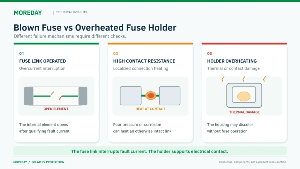
A fuse holder can overheat without the fuse link operating.
For example, a poor electrical connection may generate substantial localized heat even though the current through the fuse remains within its normal range.
This distinction is essential during troubleshooting.
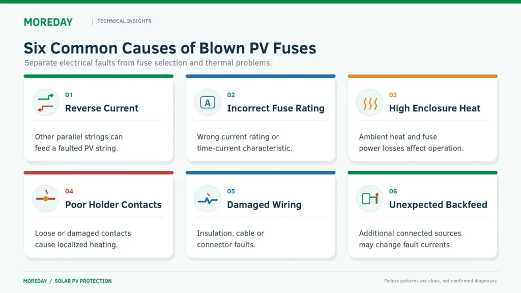
Six Common Reasons Solar PV Fuses Keep Blowing
The most effective troubleshooting process starts by identifying the possible fault mechanisms rather than immediately replacing the fuse.
Cause 1: Excessive Reverse Current from Parallel PV Strings
Reverse current is an important fault condition in photovoltaic arrays.
When several PV strings are connected in parallel, a faulted string may receive current from the remaining healthy strings.
The current contributed by other strings can exceed the faulted string’s module or conductor protection limits.
Consider a simplified example involving four identical strings, each with an STC short-circuit current of 13A.
If one string becomes faulted, the remaining three strings may contribute approximately:
Ireverse ≈ (4 − 1) × 13A = 39A
This calculation is only a preliminary estimate. Actual fault current depends on irradiance, circuit configuration and additional connected sources.
If a string is protected by a 25A gPV fuse, the resulting current may cause it to operate, depending on the fuse’s time-current characteristics and the duration of the fault.
A 39A current does not mean that every 25A fuse will open immediately.
What engineers should verify: The actual fault-current path, parallel string configuration, module maximum series fuse rating and protective-device operating characteristics.
For a detailed explanation, see When Are String Fuses Required in Solar PV Systems?.
Cause 2: Incorrect Fuse Current Rating or Characteristics
A fuse with an unsuitable current rating may open during operating conditions that should otherwise be acceptable.
For example, a fuse selected only from the module’s maximum power current (Imp) may not satisfy the relevant PV source-circuit requirements.
The correct selection must consider:
- Module short-circuit current (Isc).
- Module maximum series fuse rating.
- Expected operating and fault currents.
- Conductor protection requirements.
- Fuse time-current characteristics.
- Environmental and installation conditions.
A fuse’s rated current is not an instantaneous operating threshold.
A 20A fuse does not necessarily open immediately at 21A.
Similarly, selecting a 30A fuse instead of a repeatedly operating 20A fuse is not an acceptable troubleshooting method unless a complete protection review establishes that the higher rating is appropriate.
The larger fuse may no longer adequately protect the PV modules, conductors or connected equipment.
For detailed calculation methods, read How to Size a Solar PV Fuse.
Cause 3: Excessive Temperature Inside the Combiner Box
Solar DC combiner boxes are often exposed to high ambient temperatures and direct sunlight.
Additional heat is generated inside the enclosure by fuse links, contacts, terminals, busbars and other current-carrying components.
As temperature rises, the operating characteristics and current-carrying capability of some fuse links can change.
The fuse manufacturer’s temperature correction information must be considered.
Possible thermal contributing factors include:
- High ambient temperature.
- Solar heating of the enclosure.
- Insufficient heat dissipation.
- Closely spaced fuse holders.
- Excessive continuous loading.
- Unsuitable fuse-link power dissipation.
- Local heating from poor electrical connections.
A fuse that operates repeatedly during hot afternoons but remains intact during cooler periods may require an investigation of temperature and operating current.
However, this pattern does not prove that ambient temperature is the only cause. Solar irradiance and PV current can also increase during these periods.
Cause 4: Loose or Damaged Fuse Holder Connections
Poor electrical connections can create localized heating.
Common causes include:
- Loose terminal connections.
- Damaged or weakened fuse contacts.
- Corrosion or contamination.
- Incorrect fuse-link dimensions.
- Improper conductor termination.
- Components that are not compatible with one another.
Electrical heating at a resistive connection is approximately related to:
P = I² × R
Where:
- P = heat generated at the connection.
- I = current through the connection.
- R = contact resistance.
Even a relatively small increase in contact resistance can produce considerable localized heating when current is flowing.
This may damage the holder or transfer heat into the fuse assembly.
Under some conditions, excessive local heating can contribute to unexpected fuse operation.
However, a hot holder does not necessarily mean the fuse itself has opened.
What engineers should verify: The holder’s contact condition, termination requirements, permitted fuse links, thermal ratings and signs of deterioration, following proper isolation procedures.
For more information, see MOREDAY’s DIN Rail DC Fuse Holder Selection Guide.
Cause 5: Damaged Wiring, Connectors or Insulation
Physical damage or deteriorated insulation can create unintended electrical paths.
Potential problems include:
- Damaged PV cable insulation.
- Moisture inside electrical enclosures.
- Contaminated or damaged connectors.
- Cable abrasion.
- Improper terminations.
- Faults involving module wiring or junction boxes.
- Incorrectly assembled electrical connections.
Depending on the circuit configuration, these defects can create overcurrent conditions or other hazardous faults.
Not every insulation or ground fault will produce enough overcurrent to operate a fuse.
Some faults must be detected through other protective functions or diagnostic methods.
Therefore, repeated fuse operation should be investigated together with inverter fault messages, ground-fault indications and the complete system architecture.
Cause 6: Incorrect Circuit Configuration or Additional Current Sources
PV systems may include multiple power-conversion devices, optimizers, inverters or energy storage equipment.
The effect of these devices depends on the actual electrical topology.
A connected source capable of supplying current into a faulted PV circuit can change the available fault current.
Incorrect wiring, incompatible equipment or an unanticipated backfeed condition can also affect protection coordination.
A fuse that previously worked correctly may begin operating after a system modification if the protection design was not re-evaluated.
What engineers should verify: The updated single-line diagram, installed equipment, actual current sources and the protective-device coordination requirements.
A fuse designed for conventional PV string protection should not automatically be treated as suitable for every battery or industrial DC circuit.
How to Identify the Likely Cause from Fuse Failure Symptoms
Different operating patterns can help narrow down the investigation.
The following table provides preliminary diagnostic guidance.
| Observed Symptom | Possible Causes | Engineering Check |
|---|---|---|
| Fuse opens immediately after the circuit is restored | Persistent fault, incorrect device selection or unexpected current source | Review circuit fault records and protection arrangement |
| Fuse opens during high solar production | Increased current, temperature effects or fault conditions dependent on irradiance | Compare current, irradiance and temperature records |
| Fuse opens repeatedly in the same string | String-specific wiring fault, reverse-current condition or damaged connection | Assess the affected string and its protective circuit |
| Multiple fuses open during the same event | Common fault source, system configuration or coordination issue | Review shared circuits and event logs |
| Fuse holder is discolored or melted | High contact resistance, terminal damage or thermal overload | Inspect holder and connection integrity after safe isolation |
| Fuse appears intact, but the string has no output | Open circuit, connection defect or another equipment fault | Verify circuit condition using approved diagnostic procedures |
| Fuse opens after equipment replacement | Changed operating conditions, mismatched rating or wiring configuration | Review the new components and updated design |
These symptoms indicate possible causes, not confirmed diagnoses.
Fuse Blows Immediately After Replacement
When a new fuse opens as soon as the system is restored, a persistent fault or unsuitable protective arrangement should be suspected.
Repeatedly replacing fuses without investigating the cause can expose equipment and personnel to unnecessary risk.
Further operation should be suspended until the fault has been properly assessed.
Fuse Blows Only During Peak Sunlight
High irradiance can increase PV current compared with typical operating conditions.
At the same time, combiner box temperatures may rise.
Engineers should compare the relevant operating records with the fuse manufacturer’s current and temperature limits.
It is important to investigate whether the problem is related to excessive current, thermal conditions, or a fault that appears only under particular operating circumstances.
Only One String Keeps Blowing Fuses
Repeated operation in one string suggests that a string-specific issue may be present.
However, the current causing the fuse to operate could originate from other parallel strings.
This means the investigation should not be limited to the physical fuse position.
The complete fault-current path must be reviewed.
Fuse Holder Melts but the Fuse Remains Intact
This pattern strongly suggests that localized heating deserves investigation.
Possible factors include poor contact pressure, damaged terminals, incompatible fuse links and excessive heat dissipation.
A fuse cannot be relied upon to interrupt every high-resistance connection fault because such a fault may not produce sufficient overcurrent.
Any visibly heat-damaged holder must be assessed for replacement, and the underlying cause must be corrected.
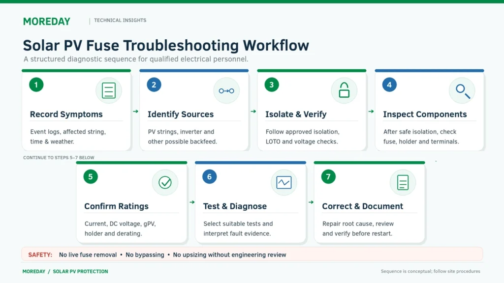
How to Troubleshoot a Repeatedly Blowing PV Fuse Safely
Solar PV circuits can remain energized while illuminated, even after other parts of the system have been switched off.
Fault investigation must therefore be carried out by qualified electrical personnel using the applicable safety procedures and equipment manufacturer’s instructions.
Do not open ordinary fuse holders under load, bypass a fuse, or repeatedly re-energize a circuit with an unresolved fault.
Step 1: Record the Failure Conditions
Before examining the circuit, collect the available operating information.
Useful records include:
- Time and frequency of fuse operation.
- Affected string or combiner input.
- Inverter alarms and event history.
- Operating current and voltage trends.
- Environmental and enclosure temperatures.
- Recent maintenance or equipment modifications.
- Photographs of visible damage.
These records can help distinguish recurring electrical faults from problems associated with particular operating conditions.
Step 2: Establish an Electrically Safe Work Condition
Qualified personnel must identify all relevant energy sources and apply the required isolation, lockout/tagout and verification procedures.
The presence of PV modules introduces special considerations because illuminated modules can continue producing hazardous DC voltage.
Opening a downstream disconnect does not necessarily de-energize the conductors connected to the PV array.
Any work involving exposed conductors, fuse holders or internal electrical connections requires a suitable risk assessment and approved work procedure.
Step 3: Examine the Fuse and Holder After Safe Isolation
Once the relevant equipment has been made safe for inspection, maintenance personnel should assess the physical condition of the components.
Possible warning signs include:
- Cracked fuse bodies.
- Discolored fuse end caps.
- Damaged holder contacts.
- Deformed or melted insulation.
- Signs of corrosion or moisture.
- Loose or damaged terminals.
An operated fuse should not automatically be interpreted as a defective component.
The inspection must determine whether the fuse performed its intended protective function or was exposed to unsuitable operating conditions.
Step 4: Verify Circuit and Component Specifications
Compare the installed protection with the actual system design.
Confirm:
- Fuse-link rated current.
- Maximum required DC voltage.
- Appropriate PV utilization category.
- Fuse breaking capacity.
- Time-current characteristics.
- Module maximum series fuse rating.
- Corrected conductor ampacity.
- Fuse-holder compatibility.
- Applicable ambient-temperature corrections.
Do not substitute a larger fuse simply to prevent repeated operation.
Step 5: Perform Appropriate Electrical Tests
Qualified personnel may need to assess circuit continuity, insulation condition, conductor integrity and other electrical characteristics.
The tests must be selected according to the system design and equipment manufacturers’ instructions.
Sensitive electronic equipment, surge protective devices and other connected components may require specific precautions or disconnection before certain tests.
Electrical measurements on energized equipment must not be performed merely to follow a generic troubleshooting checklist.
Any necessary live testing requires an appropriate risk assessment, authorized personnel and suitable test equipment.
Step 6: Correct the Root Cause Before Restoration
After identifying the cause, the appropriate corrective action may involve repairing damaged wiring, replacing a defective holder, correcting terminal connections, revising thermal arrangements or selecting the proper fuse.
The replacement fuse must meet the circuit’s actual protection requirements.
Before the circuit is returned to service, the relevant checks and commissioning procedures must be completed.
If the cause cannot be established, the circuit should remain out of service until a qualified specialist determines that restoration is safe.
Why Does a Solar Fuse Holder Overheat Without Blowing the Fuse?
A fuse holder can become damaged by localized heating without the overcurrent protective element operating.
This is particularly relevant in solar combiner boxes where multiple fuse holders may carry current for long periods.
Contact Resistance and Local Heating
The holder contacts and terminals form part of the electrical current path.
If the connection resistance increases, additional heat may develop at that location.
A loose or corroded terminal can therefore become significantly hotter than a similar connection carrying comparable current.
The problem may remain localized rather than producing an overcurrent large enough to operate the fuse.
This is why the absence of a blown fuse does not establish that the holder is operating safely.
Fuse-Link and Holder Compatibility
A cylindrical fuse may physically fit inside a holder while still being unsuitable for the complete application.
The important factors include:
- Contact dimensions and engagement.
- Rated current.
- Permitted fuse-link type.
- Power dissipation.
- Temperature limitations.
- Terminal arrangement.
- Manufacturer-approved component combinations.
A holder intended for 10×38 mm fuse links cannot be assumed suitable for a different cylindrical fuse format.
Similarly, matching the fuse dimensions does not establish complete thermal compatibility.
Thermal Imaging and Inspection
Infrared thermography can help trained personnel identify abnormal heating patterns.
For example, a connection that is substantially hotter than comparable connections under similar operating conditions may require further investigation.
However, thermal images do not independently determine the cause of an electrical fault.
Temperature readings must be interpreted alongside loading, emissivity, surrounding conditions and equipment construction.
Thermal inspection of energized equipment must be performed only under an appropriately controlled and authorized procedure.
For additional discussion of electrical connection heating, see Fluke’s Electrical Fire Prevention and Inspection Guide.
How to Prevent Solar PV Fuses from Blowing Repeatedly
Preventing repeated fuse operation requires correct equipment selection, suitable installation practices and regular maintenance.
Use the Correct gPV Fuse Characteristics
For photovoltaic circuits requiring PV-specific overcurrent protection, the selected fuse should have the appropriate characteristics and ratings.
IEC 60269-6 establishes supplementary requirements for photovoltaic fuse links.
A general-purpose DC fuse should not automatically replace a gPV fuse simply because it has the same rated current and voltage.
The selected fuse must also have suitable time-current characteristics for the intended protection.
Verify Current and Voltage Ratings
The fuse current rating must support normal operating conditions while remaining compatible with the protected equipment and conductor limits.
The rated DC voltage must be suitable for the maximum voltage the fuse may need to interrupt.
A voltage rating that is too low is a serious safety concern, but it should not automatically be identified as the cause of repeated fuse opening.
Current rating, temperature and operating characteristics are generally more relevant to an unexpected opening pattern.
The maximum system voltage still needs to be verified independently.
Improve Fuse Holder and Enclosure Conditions
Suitable installation measures may include:
- Using manufacturer-approved fuse and holder combinations.
- Following specified terminal connection requirements.
- Providing adequate enclosure space.
- Accounting for ambient temperature and solar heating.
- Maintaining suitable environmental protection.
- Replacing damaged or deteriorated connections.
The complete electrical assembly must be assessed rather than focusing exclusively on the fuse link.
Maintain Accurate System Documentation
Electrical designs should be updated whenever the PV configuration or connected equipment changes.
Important records include the module datasheets, circuit diagram, string arrangement, fuse references, protective-device ratings and maintenance history.
This documentation helps engineers investigate repeated faults and avoid incorrect replacement components.
Never Increase the Fuse Rating Without Engineering Verification
Replacing a repeatedly blowing 20A fuse with a 25A or 30A fuse may appear to solve the immediate problem.
However, a higher rating can compromise protection if it exceeds the limits of the modules, conductors or equipment.
The appropriate response is to determine why the installed fuse is operating and whether the entire protection design is correct.
Fuse rating changes must be justified by the relevant electrical calculations and product documentation.
MOREDAY PV Fuse Solutions and Maintenance Checklist
MOREDAY supplies photovoltaic DC fuse links and holders for solar protection applications, including product families with 1000V and 1500V DC ratings.
Where fuse links or holders require replacement, the correct model should be determined from the existing equipment specifications and an updated protection assessment.
MOREDAY DC Fuse Links
The MOREDAY 1000V/1500V DC Fuse Link Range includes cylindrical fuse configurations for PV protection applications.
Different fuse-link dimensions and current ratings are available within the broader product family.
The exact model’s current rating, DC voltage, breaking capacity, application characteristics and compatibility should be verified before procurement.
A generic 1000V or 1500V product description is not sufficient to establish suitability for a particular replacement.
MOREDAY DC Fuse Holders
Relevant holder families include:
- MDPV-30 1000V DC Fuse Holder, associated with 10×38 mm cylindrical fuse links.
- MDPV-32 1500V DC Fuse Holder, associated with 10×85 mm cylindrical fuse links.
These configurations are product-family examples.
The actual holder and fuse-link combination must be verified from the relevant technical documentation.
PV Fuse Troubleshooting Checklist
| Check | Information Required |
|---|---|
| Failure history | Time, frequency and affected fuse position |
| PV configuration | Number of strings, modules and connected sources |
| Module specifications | Isc, Voc and maximum series fuse rating |
| Fuse link | Current, voltage, category and breaking capacity |
| Fuse holder | Dimensions, current rating, contact and terminal compatibility |
| Fault-current paths | Possible reverse current and other source contributions |
| Temperature | Enclosure conditions, loading and thermal restrictions |
| Wiring and connections | Physical condition and relevant test results |
| Standards | Applicable IEC, NEC, UL and project requirements |
| Corrective action | Documented cause, repair and verification results |
The information collected should support a documented engineering decision before the system is restored to service.
Request Technical Support from MOREDAY
For EPC contractors, maintenance teams, distributors and OEM customers, useful information includes:
PV system configuration → Fuse model → System voltage → Current rating → Failure symptoms → Installation conditions → Required replacement components
Photographs of the affected components and the relevant technical documentation can also help identify possible compatibility or installation problems.
Explore the MOREDAY DC Fuse Product Range or contact MOREDAY for model-specific fuse links, fuse holders and technical selection support.
Conclusion
A solar PV fuse that repeatedly blows should not be treated as an isolated component failure.
Possible causes include genuine overcurrent faults, reverse-current conditions, incorrect fuse selection, excessive temperature, unsuitable holder connections and damaged wiring.
The most effective troubleshooting approach is to identify the failure pattern, evaluate the actual fault-current sources, inspect the complete fuse assembly under safe conditions, and verify the protection requirements.
For reliable PV operation, the fuse link, holder, wiring and complete electrical system must be correctly coordinated.
Replacing a fuse without identifying the root cause—or installing a higher-rated fuse to prevent further opening—can create additional electrical hazards.