
DistributionSolar
A fuse holder is an electrical component designed to securely mount a fuse link and connect it to an electrical circuit. It provides the mechanical support, conductive contacts, and insulation needed for the fuse to operate within its specified conditions.
The fuse holder itself does not normally interrupt an overcurrent fault. Instead, the fuse link installed inside the holder contains a calibrated element that melts and interrupts the circuit when sufficient overcurrent occurs.
Fuse holders are used in industrial control panels, electrical distribution equipment, solar photovoltaic (PV) systems, and many other applications. Their design varies according to the fuse type, voltage, current, mounting method, and installation environment.
This guide explains how fuse holders work, their main components, common types, and the important safety and compatibility considerations engineers should understand.

What Is a Fuse Holder?
A fuse holder is the mounting and connection interface for a replaceable fuse link.
It is designed to keep the fuse in the correct position and maintain reliable electrical contact between the fuse terminals and the external circuit.
Under the terminology used in IEC 60269-1, a fuse holder consists of a fuse base and a fuse carrier where those components are applicable.
Different product designs may use fixed contacts, removable carriers, hinged compartments, or other mounting arrangements.
What Is the Purpose of a Fuse Holder?
A properly selected fuse holder performs several important functions:
- Mechanical support: Keeps the fuse link securely positioned.
- Electrical connection: Provides a conductive path between the fuse and the circuit.
- Insulation: Helps prevent unintended contact between conductive parts within its specified design.
- Fuse replacement: Allows a compatible fuse link to be installed or replaced according to the manufacturer’s instructions.
- Equipment integration: Supports installation in control panels, distribution equipment, or protective enclosures.
Some fuse holders also include indicators that help identify whether the fuse has operated.
However, indication features do not automatically provide a reliable means of verifying that a circuit is de-energized.
Does a Fuse Holder Protect Against Overcurrent?
The fuse holder and fuse link perform different functions.
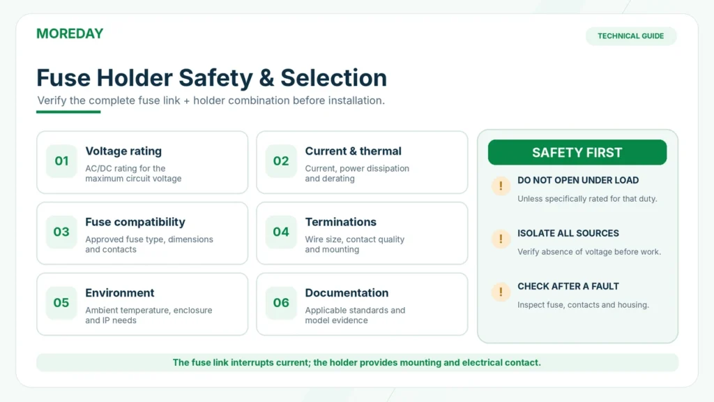
The fuse link interrupts qualifying overcurrent. The holder provides the electrical and mechanical interface required for that fuse to operate.
For example, a 25A gPV fuse link may be installed in a compatible photovoltaic fuse holder.
If a qualifying fault current occurs, the fuse element may melt and interrupt the current according to its operating characteristics.
The holder does not independently detect or interrupt the fault.
This distinction is important when evaluating circuit protection specifications.
For an introduction to fuse-link operation, see What Is a DC Fuse? How It Works, Types, Ratings & Solar PV Uses.
How Does a Fuse Holder Work?
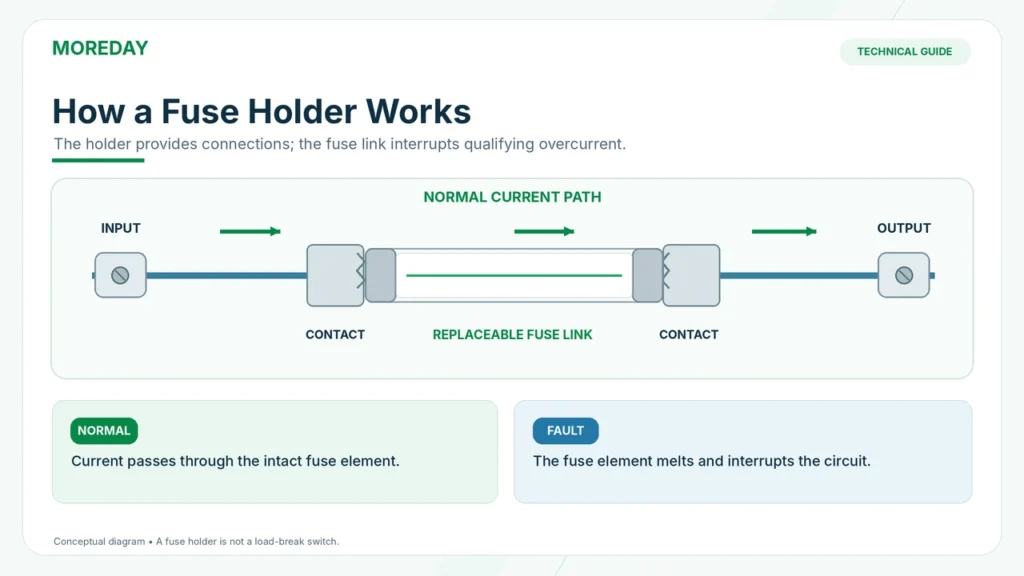
A fuse holder works by creating a continuous electrical connection through an installed fuse link.
When the fuse is correctly installed, current enters the holder through one terminal, passes through its conductive contacts and the fuse element, and exits through the opposite terminal.
Electrical Current Path
For a typical two-terminal cartridge fuse holder, the current path can be represented as:
Input terminal → Holder contact → Fuse end cap → Fuse element → Opposite end cap → Holder contact → Output terminal
This arrangement allows the fuse element to form part of the protected electrical circuit.
The holder contacts must maintain sufficiently low electrical resistance under their specified operating conditions.
Poor contact can generate unwanted heat, even when the fuse itself remains intact.
What Happens During Normal Operation?
Under normal conditions, the fuse carries the operating current through its internal element.
The holder’s conductive components maintain the connection between the fuse and the external wiring.
A properly selected holder must be capable of carrying the required current under the applicable installation and temperature conditions.
The fuse and holder may generate some heat because of their electrical resistance.
The acceptable temperature rise depends on the actual design, current, contact resistance, and environmental conditions.
What Happens When the Fuse Blows?
If sufficient overcurrent flows for the required duration, the fuse element melts.
The fuse must then extinguish the resulting arc and interrupt the current within its rated capabilities.
After successful interruption:
- The internal fuse element is no longer electrically continuous.
- Current through that fuse link is interrupted.
- The holder remains physically installed.
- The operated fuse link must be replaced after the fault has been investigated.
The holder may remain serviceable if it has not been damaged and the manufacturer permits continued use.
However, overheating, contact damage, deformation, or other abnormal conditions may require replacement of the holder as well.
Can a Fuse Holder Be Opened Under Load?
Not unless the complete device is specifically rated for that operation.
Many conventional cartridge fuse holders are not designed to interrupt load current when their carriers are opened.
Opening an unsuitable holder under load can create hazardous arcing.
This is particularly important in DC photovoltaic systems, where current does not have the periodic natural zero crossings found in AC circuits.
A fuse holder must not be treated as a load-break switch or an isolator unless its verified ratings explicitly permit that function.
Main Components of a Fuse Holder
Although fuse holder designs vary, most include several important mechanical and electrical components.
| Component | Function | Key Consideration |
|---|---|---|
| Fuse base | Fixed supporting structure | Mounting and insulation |
| Fuse carrier | Holds the replaceable fuse link where applicable | Compatible design and secure positioning |
| Fuse contacts | Connect the fuse link to the circuit | Contact pressure and resistance |
| Terminals | Connect external conductors | Wire size, termination method, and tightening requirements |
| Insulating housing | Separates conductive parts and provides structural support | Voltage, temperature, and environmental suitability |
| Indicator, if provided | Indicates a specified fuse or circuit condition | Indicator behavior and limitations |
Fuse Base and Carrier
The fuse base is generally the fixed portion of the holder.
A fuse carrier, where present, supports the removable fuse link.
Together, these components maintain the required positioning and electrical contact.
Some cylindrical fuse holders use hinged carriers, while other products use removable caps or fixed fuse clips.
Contacts and Terminals
The contacts are important to the holder’s electrical performance.
Their purpose is to create a reliable connection with the fuse link’s end caps or terminals.
Contact quality, pressure, alignment, and resistance all influence heating and long-term reliability.
The external terminals connect the holder to the circuit conductors.
Incorrect conductor sizes, damaged terminals, or improper tightening can create excessive resistance and local heating.
Insulating Housing
The insulating housing helps separate live conductive components and provides the structural support needed for installation.
Its suitability depends on the specified voltage, thermal conditions, and installation environment.
A plastic housing should not automatically be assumed suitable for outdoor exposure, high humidity, elevated temperature, or direct sunlight.
Those characteristics must be supported by the holder’s technical documentation and the complete enclosure design.
Fuse Status Indicators
Some fuse holders include visual indicators intended to help identify an operated fuse.
Depending on the product, the indication may be mechanical or electrical.
An indicator should not be interpreted as an independent voltage detector.
A circuit may remain energized on one or both sides of an operated fuse, particularly in systems with multiple sources.
Qualified personnel must verify the electrical state using suitable procedures and instruments before maintenance.
What Are the Main Types of Fuse Holders?
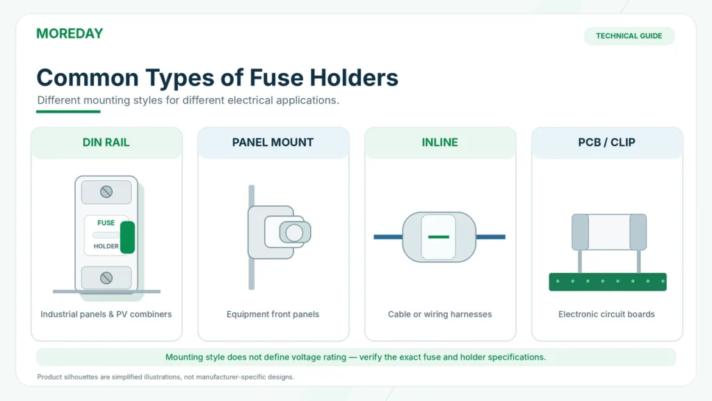
Fuse holders are available in different designs for different mounting arrangements and electrical applications.
The most common types include DIN rail, panel-mount, inline, PCB, and fuse-block configurations.
DIN Rail Fuse Holders
DIN rail fuse holders are commonly used inside industrial control panels, distribution boards, and solar DC combiner boxes.
They mount onto a compatible metal rail and allow protective components to be arranged in an organized panel layout.
Their advantages may include compact installation, modular arrangement, and accessible fuse positions.
However, the correct product must still be selected according to voltage, current, fuse dimensions, temperature, and mounting requirements.
For more detailed selection guidance, see How to Choose the Right DIN Rail Fuse Holder.
Panel-Mount Fuse Holders
Panel-mount fuse holders are installed through a panel or equipment enclosure.
They are commonly used in electronic equipment, control instruments, and other electrical assemblies.
Some designs allow fuse replacement from the panel exterior.
Accessibility does not mean that a fuse may be replaced while the equipment is energized.
The appropriate isolation and replacement procedure must still be followed.
Inline Fuse Holders
Inline fuse holders are incorporated into a cable or wiring harness.
They are often found in automotive, low-voltage equipment, and certain specialized DC applications.
Their suitability depends on their electrical ratings, construction, environmental protection, and intended installation.
An inline holder intended for a low-voltage automotive fuse must not be substituted for a high-voltage PV fuse holder.
PCB Fuse Holders and Fuse Clips
Printed circuit board fuse holders are designed to mount directly on electronic circuit boards.
Some use enclosed fuse carriers, while others use exposed clips that hold a replaceable fuse.
These products are commonly associated with electronic equipment and control circuitry.
Contact accessibility, insulation, and fuse type vary significantly across designs.
Fuse Blocks
Fuse blocks provide multiple fuse positions within a single mounting arrangement.
They may be used in distribution equipment, industrial panels, or wiring systems with several protected circuits.
Each fuse position must be properly rated, and the complete assembly must be suitable for the total electrical and thermal loading.
Comparison of Common Fuse Holder Types
| Type | Typical Mounting | Common Application |
|---|---|---|
| DIN rail holder | Standardized mounting rail | Industrial panels and PV combiner boxes |
| Panel-mount holder | Equipment panel | Electronic and control equipment |
| Inline holder | Cable or wiring harness | Low-voltage and specialized DC circuits |
| PCB holder or clip | Printed circuit board | Electronic equipment |
| Fuse block | Equipment chassis or distribution assembly | Multi-circuit electrical protection |
These categories describe mounting designs, not universally interchangeable electrical ratings.
Fuse Holder vs Fuse Link vs Fuse Disconnect Switch
The terms fuse holder, fuse link, and fuse disconnect switch are sometimes confused.
Although they may appear together in the same electrical system, they perform different functions.
Fuse Link vs Fuse Holder
A fuse link contains the current-interrupting element.
A fuse holder supports the fuse link and connects it to the circuit.
The correct protection arrangement depends on the compatibility of these components.
| Feature | Fuse Link | Fuse Holder |
|---|---|---|
| Contains the fusible element | Yes | No |
| Interrupts qualifying overcurrent | Yes | Not independently |
| Provides a mounting interface | Not its primary function | Yes |
| Replaceable after fuse operation | Yes | Only if damaged or otherwise unsuitable |
| Rated current and voltage | Specified for the fuse link | Specified for the holder |
| Breaking capacity | Defined for the fuse link under specified conditions | Must be assessed through applicable holder/assembly compatibility and ratings |
A holder must not be described as having the independent current-interrupting capability of the fuse link installed inside it.
Fuse Holder vs Fuse Disconnect Switch
A fuse disconnect switch combines functions that may include fuse accommodation and specified switching or isolation capabilities.
Its permitted operations depend on its construction and tested ratings.
A conventional fuse holder does not automatically provide those capabilities.
For this reason, a hinged cover or removable fuse carrier should not be assumed to provide load-break functionality.
Fuse Holder vs Circuit Breaker
A circuit breaker contains a mechanical operating and protective system designed to interrupt specified electrical currents.
A fuse holder does not perform the same protective operation by itself.
An appropriately rated circuit breaker may also have specified switching or isolation capabilities.
Choosing between fuses and circuit breakers requires an assessment of the circuit’s actual protection requirements.
For a related technical comparison, see DC MCB vs DC Fuse: Which Is Better for Solar PV Protection?.
What Should You Check When Choosing a Fuse Holder?
Although the detailed selection process depends on the application, several basic requirements apply to almost every fuse holder.
Voltage and Current Ratings
Confirm that the fuse holder has appropriate ratings for the intended AC or DC circuit.
A 1000V DC-rated holder cannot be assumed suitable for a circuit requiring a 1500V DC rating.
The rated current must also be compatible with the fuse link and the installation conditions.
The holder’s current rating should not be confused with the rated current of the replaceable fuse.
Fuse Compatibility
Check the required fuse-link type, dimensions, and manufacturer’s compatible references.
For example, cylindrical fuse links are available in different lengths and diameters.
Common PV formats include:
- 10 × 38 mm
- 10 × 65 mm
- 10 × 85 mm
Matching dimensions alone does not prove electrical compatibility.
The fuse link must also have the required voltage, current, operating characteristic, and breaking capacity.
AC or DC Application
Do not assume a holder rated for AC service is automatically suitable for a DC installation.
Use a holder with the required manufacturer-specified DC ratings and application documentation.
For solar PV systems, consider the characteristics of the intended gPV fuse link and the complete protection assembly.
Contact and Terminal Design
Examine the compatible conductor sizes, terminal configuration, and installation requirements.
Incorrect terminations can lead to high contact resistance and overheating.
Tightening torque, conductor preparation, and the use of ferrules or other accessories must follow the manufacturer’s instructions.
Temperature and Environmental Conditions
Fuse holders may be installed in warm control cabinets or outdoor electrical enclosures.
Important considerations include ambient temperature, ventilation, device spacing, enclosure heating, and conductor loading.
A holder’s permissible current may be affected by the installed fuse link and its power dissipation.
Any necessary derating should be based on the actual manufacturer’s guidance and applicable assembly requirements.
Standards and Technical Documentation
IEC 60269-1:2024 provides general requirements for low-voltage fuses within its specified scope, including relevant terminology and component requirements.
For North American applications, UL 4248-1 establishes general requirements for specified fuse holders and accessories.
Photovoltaic fuse links have additional requirements addressed by IEC 60269-6.
The exact applicable standards depend on the fuse holder, fuse link, equipment, and intended market.
A manufacturer’s reference to an IEC or UL standard does not automatically establish independent certification of every product in a series.
Fuse Holder Safety, Maintenance and Solar PV Applications
Fuse holders are important components in reliable electrical protection systems, but incorrect installation or maintenance can create serious safety risks.
Common Fuse Holder Problems
| Problem | Possible Causes | Recommended Assessment |
|---|---|---|
| Holder overheating | Contact resistance, excessive current, poor termination or ventilation | Isolate and inspect the complete assembly |
| Discolored housing | Excessive temperature or aging | Check damage, ratings and operating conditions |
| Loose fuse contact | Incorrect fuse, worn contacts or mechanical damage | Verify compatible components and replace damaged parts |
| Repeated fuse operation | Circuit fault, incorrect rating or unsuitable coordination | Investigate fault and review protection design |
| Indicator inconsistency | Indicator design, wiring condition or device failure | Verify fuse continuity and circuit status using suitable methods |
Overheating can occur even when the fuse link has not operated.
This is because local heating at a damaged or high-resistance connection may not produce enough circuit current to cause the fuse element to melt.
A melted fuse holder therefore does not necessarily indicate that the fuse itself was incorrectly rated.
Safe Fuse Replacement
Fuse replacement should be performed only by appropriately qualified personnel following the equipment manufacturer’s instructions and the applicable safety procedures.
The necessary precautions include:
- Identifying and isolating all relevant sources of electrical energy.
- Applying the required lockout/tagout procedures.
- Verifying the absence of hazardous voltage with suitable equipment.
- Investigating the cause of the fuse operation.
- Checking the holder for damage and installing the specified replacement components.
PV circuits deserve particular attention because modules can continue producing voltage whenever illuminated.
Opening a fuse holder or removing a fuse link must not be treated as proof that the circuit has been made safe.
If the holder or contacts are damaged, replacing the fuse link alone may be insufficient.
Fuse Holders in Solar PV Systems
Solar combiner boxes often incorporate fuse holders for individual PV string protection where overcurrent devices are required.
The fuse links can help protect against qualifying reverse-current faults when several strings are connected in parallel.
The holder provides the mounting and connection interface for those fuse links.
Not every solar string requires individual overcurrent protection, and the presence of a fuse holder does not establish that its installed fuse is correctly selected.
The final design must consider module ratings, string configuration, fault currents, conductor capacity, and applicable standards.
For system-specific details, see How to Select Fuses for Solar Combiner Boxes.
MOREDAY DC Fuse Holder Options
MOREDAY supplies photovoltaic fuse links and holders for solar DC protection applications.
Examples from the published product range include:
| Product Family | Published Voltage Class | Compatible Fuse Dimensions |
|---|---|---|
| MDPV-30 | 1000V DC | 10 × 38 mm |
| MDPV-32 | 1500V DC | 10 × 85 mm |
| MDPV2-32 | 1500V DC | 10 × 65 mm |
These are product-family examples and do not establish universal compatibility for every fuse link of the stated dimensions.
Engineers should verify the actual holder model, rated current, terminal configuration, installation conditions, and compatible fuse references.
Relevant MOREDAY product resources include:
- MDPV-30 1000V DC Fuse Holder
- MDPV-32 1500V DC Fuse Holder
- MOREDAY DC Fuse and Fuse Holder Product Range
Technical Support and Procurement
When requesting fuse holders for a new electrical system, provide the application, maximum circuit voltage, operating current, selected fuse-link type, required dimensions, mounting arrangement, and applicable compliance requirements.
For solar PV projects, include the system configuration and the intended fuse protection characteristics.
This helps ensure the holder and fuse link are evaluated as compatible components rather than selected independently.
Conclusion
A fuse holder provides the mechanical support, electrical contacts, and insulation needed to install a fuse link in an electrical circuit.
The fuse link performs the overcurrent interruption, while the holder provides the connection and mounting interface.
Understanding this distinction helps engineers avoid common mistakes involving incompatible fuse sizes, incorrect voltage ratings, poor contact conditions, and unsafe switching practices.
Whether the application involves industrial control equipment or solar PV protection, selecting a suitable fuse holder requires checking the complete circuit and component specifications.
Explore MOREDAY’s DC Fuse Solutions for photovoltaic fuse links, fuse holders, and related electrical protection equipment.