
DistributionSolar
The main difference between a DC fuse and an AC fuse is how each device interrupts fault current under its specified electrical conditions. Alternating current periodically passes through zero, which helps extinguish the electrical arc formed when a fuse operates. Direct current has no equivalent periodic current-zero crossing, making arc interruption more demanding.
However, this does not mean every AC fuse is unsuitable for DC applications. Some fuse links have separate AC and DC ratings and can be used in either type of circuit within their specified limits.
The correct selection depends on rated voltage, breaking capacity, operating characteristics, and circuit conditions—not simply whether the fuse is described as an AC or DC model.
This guide compares DC and AC fuses, explains their technical differences, and clarifies when they can be used in photovoltaic and other electrical systems.
How AC and DC Currents Affect Fuse Operation
Both AC and DC fuses protect electrical circuits by interrupting qualifying overcurrents.
Their basic operating principle is similar: excessive current generates heat inside the fuse element, causing it to melt and initiate circuit interruption.
The critical difference is what happens after the element melts.
AC Current and Natural Zero Crossing
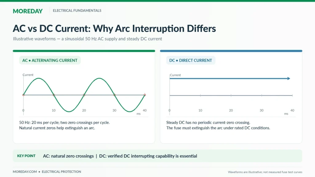
Alternating current changes direction periodically.
In a conventional 50Hz or 60Hz sinusoidal AC system, current crosses zero twice during each cycle.
- At 50Hz, current crosses zero 100 times per second.
- At 60Hz, current crosses zero 120 times per second.
These current-zero crossings help the fuse interrupt an electrical arc.
When the element melts, the arc must be extinguished and the fuse must withstand the subsequent recovery voltage.
Natural current-zero crossings assist this process, although successful interruption still depends on the fuse’s construction and tested ratings.
DC Current and Arc Interruption
In a steady DC circuit, current does not periodically reverse direction or pass through zero.
When a fuse element melts, an arc can form between the separated portions of the element.
The fuse must extinguish that arc through its internal design and interrupt the current under the specified circuit conditions.
This makes the fuse’s verified DC interrupting capability particularly important.
How a Fuse Interrupts Current
The basic operating sequence is:
Excessive current → Fuse element heating → Element melting → Arc formation → Arc extinction → Circuit interruption
Both AC and DC fuses follow this general process.
What changes is how the electrical supply, circuit inductance, and fuse construction affect arc extinction.
For a broader introduction to the device, see What Is a DC Fuse? How It Works, Types, Ratings & Solar PV Uses.
DC Fuse vs AC Fuse: Key Differences
A useful comparison must distinguish between the type of electrical supply and the actual ratings of the fuse link.
| Feature | DC Fuse Application | AC Fuse Application |
|---|---|---|
| Current waveform | Normally unidirectional | Periodically reverses direction |
| Natural current zero | No periodic current zero | Current crosses zero every half-cycle |
| Arc extinction | Must occur without periodic natural current zero | Assisted by natural current zero |
| Rated voltage | Specified in V DC | Specified in V AC |
| Breaking capacity | Must be verified for DC conditions | Must be verified for AC conditions |
| Circuit factors | DC voltage, prospective fault current, L/R time constant | AC voltage, frequency, power factor and prospective fault current |
| Operating characteristic | Must suit the DC circuit and protected equipment | Must suit the AC circuit and protected equipment |
| PV suitability | Requires suitable photovoltaic protection characteristics | AC rating alone does not establish PV suitability |
These distinctions do not necessarily require two completely different physical constructions.
Are DC Fuses Physically Different from AC Fuses?
Sometimes, but not always.
Fuse design can vary according to rated voltage, current, breaking capacity, operating characteristics, and application.
Design features may include:
- Different fuse element geometries.
- Multiple interruption points.
- Ceramic bodies and arc-quenching filler.
- Different internal spacing and insulation arrangements.
- Application-specific element designs.
However, quartz sand and other arc-quenching materials are not exclusive to DC fuses.
High-breaking-capacity AC fuses may also use them.
Similarly, it is inaccurate to claim that every DC fuse has a longer fuse element or stronger housing than every AC fuse.
Some fuse links are designed and verified for both AC and DC operation.
Does a DC Fuse Always Have a Higher Breaking Capacity?
No.
A fuse’s rated breaking capacity is determined by its tested performance under specified electrical conditions.
For example, a particular product may have a higher AC interrupting rating than its DC interrupting rating.
Another product may have different values because of its construction and test conditions.
The correct information must come from the manufacturer’s technical documentation.
A higher voltage or current rating does not automatically establish a higher breaking capacity.
AC vs DC Fuse Voltage Ratings and Breaking Capacity
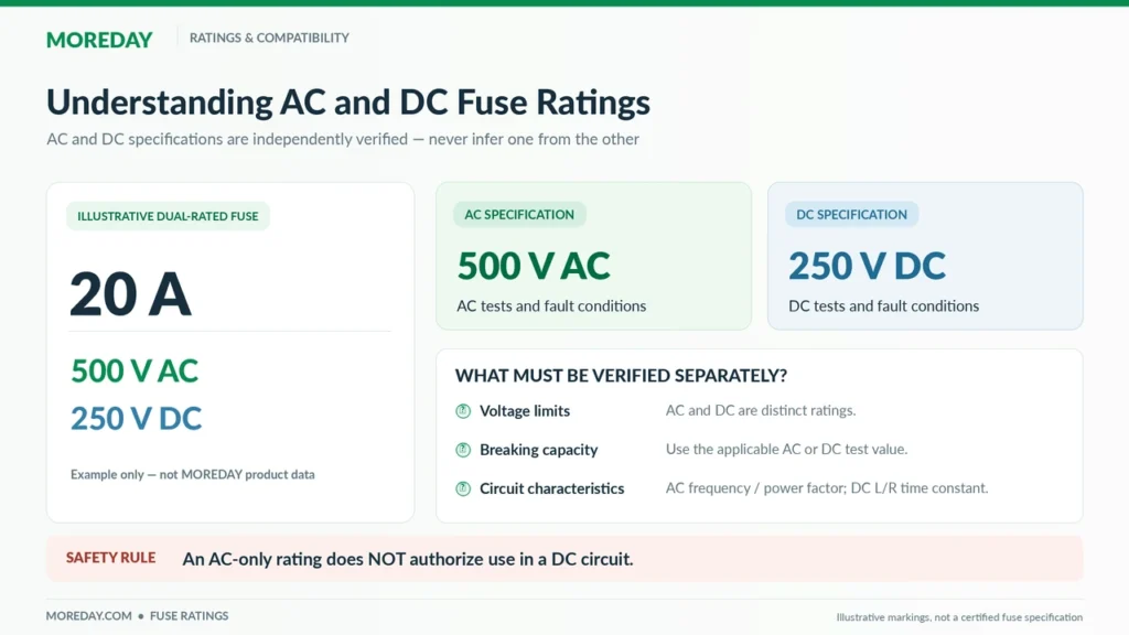
One of the most important selection mistakes is treating AC and DC voltage ratings as interchangeable.
A fuse marked 600V AC is not automatically suitable for a 600V DC circuit.
The same principle applies to 1000V AC and 1000V DC ratings.
Understanding AC and DC Voltage Markings
A fuse may be marked with one or more ratings, such as:
| Example Marking | Interpretation |
|---|---|
| 500V AC | Rated for specified AC applications up to 500V |
| 250V DC | Rated for specified DC applications up to 250V |
| 500V AC / 250V DC | Separately rated for both applications |
| 1000V DC gPV | Rated for the specified photovoltaic DC application |
These markings are illustrative, not specifications for a particular MOREDAY product.
The AC and DC ratings must be evaluated independently.
For a fuse with both ratings, engineers must also verify the relevant breaking capacities and application conditions.
What Is Fuse Breaking Capacity?
Breaking capacity is the maximum prospective current a fuse is rated to interrupt under its specified test conditions.
For example, a product may have an AC breaking capacity of 100kA and a lower DC breaking capacity.
The actual values depend on its design and rated conditions.
A fuse must not be selected using its AC breaking-capacity value when the manufacturer provides a different DC rating.
Why the DC Circuit Time Constant Matters
The DC circuit time constant is commonly expressed as:
τ = L / R
Where:
- τ is the circuit time constant in seconds.
- L is circuit inductance in henries.
- R is circuit resistance in ohms.
A circuit with a larger L/R time constant generally allows current to decay more slowly and can create more demanding interruption conditions.
The effect depends on the actual fault circuit and fuse design.
This is particularly relevant in industrial DC circuits, battery systems, and equipment with significant inductance.
Eaton’s Bussmann Series High-Speed Fuse Application Guide explains how DC voltage, circuit time constant, and prospective fault current affect fuse selection.
An AC voltage rating should never be converted into a DC rating using an arbitrary multiplier.
Only the manufacturer’s verified application data or explicit engineering approval should be used.
Can an AC Fuse Be Used in a DC Circuit?
Yes, but only when the fuse has an appropriate verified DC rating or the manufacturer explicitly approves its use under the specified DC conditions.
An AC-only rating does not establish DC suitability.
This distinction is important because some industrial fuses are sold as AC/DC devices, while others have only been tested or specified for AC operation.
When AC-Rated Fuses May Be Used for DC
A fuse can be considered for DC service if its documentation provides the necessary information, including:
- Rated DC voltage.
- DC breaking capacity or equivalent validated interruption capability.
- Applicable circuit time-constant limitations.
- Suitable operating characteristics.
- Manufacturer-approved application conditions.
For example, a fuse explicitly marked with both 500V AC and 250V DC ratings may be suitable for either circuit within its respective ratings.
Its suitability still depends on current rating, fault-current conditions, installation, and the protected equipment.
What Happens If an AC-Only Fuse Is Used in DC?
Using a fuse without a suitable DC interruption rating can result in failure to extinguish the electrical arc.
Potential consequences include:
- Sustained arcing after the element melts.
- Excessive internal heating.
- Fuse body damage or rupture.
- Damage to surrounding equipment.
- Fire or injury hazards.
These outcomes are possible failure modes, not inevitable results for every misapplication.
The risk must be evaluated from the circuit’s actual electrical conditions.
Can a DC Fuse Be Used in an AC Circuit?
The same principle applies in reverse.
A fuse marked only with DC ratings should not automatically be used in an AC circuit.
The manufacturer must specify appropriate AC voltage, frequency, breaking capacity, and operating characteristics for the intended application.
A product designed for both AC and DC can be used according to its separate verified ratings.
Is It Safe to Replace an AC Fuse with a DC Fuse of the Same Ampere Rating?
Not based on current rating alone.
For instance, two fuses rated at 20A may have different:
- Voltage ratings.
- Breaking capacities.
- Operating speeds.
- Time-current characteristics.
- Physical dimensions.
- Application approvals.
An incorrect replacement may fail to provide the intended protection even if it physically fits the fuse holder.
Replacement decisions should follow the original equipment manufacturer’s specified fuse references or a properly verified equivalent.
Why Solar PV Systems Need Specific DC Fuse Characteristics
Solar photovoltaic systems operate on DC at the module and array level.
Their electrical behavior creates protection requirements different from those of conventional AC distribution circuits.
Photovoltaic Fault Current Characteristics
Solar modules are current-limited sources.
In many PV circuits, the short-circuit current is only moderately higher than normal operating current.
When several PV strings are connected in parallel, a fault in one string may cause current from other strings to flow into the affected branch.
This is known as reverse current or backfeed current.
The resulting fault current may be too low to operate an unsuitable general-purpose fuse within the required time.
For this reason, PV protection requires attention to the fuse’s time-current behavior and its ability to interrupt relevant overcurrents at the rated DC voltage.
What Makes a gPV Fuse Different?
The gPV utilization category identifies fuse links with characteristics intended for photovoltaic applications under IEC 60269-6.
These fuse links are designed for the protection of PV strings and arrays within the applicable operating conditions.
Their selection depends on:
- Maximum PV system voltage.
- String and array current.
- Module maximum series fuse rating.
- Available fault current.
- Fuse time-current characteristics.
- Breaking capacity.
- Fuse holder and thermal compatibility.
A general-purpose DC fuse does not automatically have the required gPV characteristics.
Likewise, the gPV designation does not mean that a fuse will interrupt every possible PV fault.
Where Are PV DC Fuses Installed?
Where required by the design, PV fuse links may be installed in:
- Individual PV string circuits.
- Solar combiner boxes.
- Sub-array protection circuits.
- Other manufacturer-specified PV protection arrangements.
For example, a solar DC combiner box may contain gPV fuse links to protect individual strings against qualifying reverse-current faults.
However, not every PV installation requires a fuse on every string.
The need depends on fault-current paths, module protection limits, conductor ratings, and applicable installation rules.
For additional guidance, see When Are String Fuses Required in Solar PV Systems?.
Are PV DC Fuses Suitable for Battery Systems?
Not automatically.
Battery systems may produce much higher prospective short-circuit currents than PV strings and may have different circuit time constants.
A gPV fuse should not be considered suitable for battery energy storage protection solely because it has a high DC voltage rating.
The battery protection device must be selected for the battery circuit’s actual current, voltage, fault characteristics, and equipment requirements.
How to Choose Between AC and DC Fuses
The correct selection starts with the circuit, not the fuse’s appearance or advertised application.
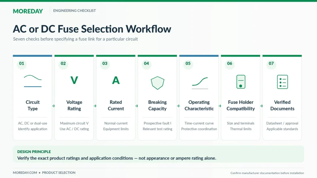
Step 1: Identify the Current Type
Determine whether the circuit operates on AC, DC, or under conditions that require both ratings.
This includes considering rectifiers, inverters, battery circuits, and other power-conversion equipment.
Step 2: Verify the Maximum Circuit Voltage
Check the highest voltage that the fuse must safely withstand or interrupt under relevant conditions.
For PV systems, maximum cold-weather string voltage can be higher than normal operating voltage.
Select a fuse with the appropriate verified AC or DC rating.
Step 3: Determine the Current Rating
Review normal operating current, permitted overcurrent protection limits, conductor capacity, and relevant environmental factors.
For solar applications, see How to Size a Solar PV Fuse: Current, Voltage & Calculation Examples.
Step 4: Check Breaking Capacity
Verify the available prospective fault current and the fuse’s breaking capacity for the relevant AC or DC application.
For DC circuits, confirm any applicable L/R time-constant restrictions.
Step 5: Evaluate the Operating Characteristic
A suitable fuse must respond appropriately to the fault conditions the protective arrangement is intended to address.
Check manufacturer time-current data, pre-arcing and clearing characteristics where necessary, and application-specific requirements.
Step 6: Verify Fuse Holder Compatibility
The fuse link and holder must be compatible.
Consider voltage and current ratings, dimensions, contact design, thermal performance, and the manufacturer’s permitted combinations.
Step 7: Confirm Standards and Documentation
Review the applicable product requirements, installation codes, manufacturer datasheets, and any required third-party listing or certification documents.
A marking that references an IEC standard should not be interpreted as independent proof of third-party certification.
The final device selection must be consistent with the relevant equipment and circuit requirements.
Applicable Standards and MOREDAY Fuse Solutions
Different fuse applications are covered by different standards and electrical installation requirements.
IEC Standards for Fuse Protection
| Standard | Main Application |
|---|---|
| IEC 60269-1:2024 | General requirements for applicable low-voltage fuses |
| IEC 60269-6:2010+A1:2021 | Supplementary requirements for photovoltaic fuse links |
| IEC 62548-1:2023+A1:2025 | PV array design, including electrical protection requirements |
These standards have different scopes.
IEC 60269-1 establishes general fuse requirements within its stated range.
IEC 60269-6 addresses the specific characteristics of fuse links used to protect photovoltaic strings and arrays.
IEC 62548-1 concerns the broader design of photovoltaic arrays.
For U.S. projects, the applicable UL product standards, NEC requirements, equipment listings, and local adoption rules must also be considered.
The manufacturer’s technical documentation remains essential for determining the suitability of an individual fuse model.
MOREDAY DC Fuse Products
MOREDAY offers DC fuse links and fuse holders for solar photovoltaic protection applications, including 1000V and 1500V DC product families.
Relevant resources include:
- MOREDAY DC Fuse Product Range
- DC Fuse Link 1000V/1500V
- Solar Combiner Box Fuse Selection Guide
- 1000V vs 1500V DC Fuses: Ratings and Selection
For each application, engineers should verify the exact fuse reference, rated current, DC voltage, breaking capacity, fuse characteristics, and compatible holder.
MOREDAY’s published product families provide a starting point for technical evaluation, but the final selection should be based on model-specific specifications and required conformity evidence.
Information to Provide for a Technical Inquiry
For PV equipment manufacturers, EPC contractors, distributors, and OEM customers, useful specification information includes:
Application → AC/DC circuit type → Maximum voltage → Operating current → Prospective fault current → Fuse characteristic → Mounting requirements → Applicable standards
Providing this information helps identify the appropriate fuse family and reduces the risk of incorrect product substitution.
Conclusion
The principal difference between AC and DC fuses lies in the electrical conditions under which fault current must be interrupted.
AC current has natural zero crossings that help extinguish an arc. DC current does not, so verified DC interruption performance is essential.
Nevertheless, AC and DC are not always mutually exclusive fuse categories. Some fuse links carry separate ratings for both types of circuits.
The correct approach is to check the actual manufacturer’s specifications rather than assume that identical current ratings or physical dimensions make two fuses interchangeable.
For solar photovoltaic applications, suitable gPV fuse links and correctly matched holders can provide the required overcurrent protection when selected according to the electrical design.
Explore MOREDAY’s DC Fuse Solutions for available photovoltaic fuse links, holders, and related protection components.