

DistributionSolar
Choosing the right DIN rail fuse holder requires more than matching the fuse size. The holder must support the required DC voltage, operating current, fuse-link dimensions, thermal conditions, and installation configuration. In solar photovoltaic (PV) systems, these requirements become especially important because of high DC voltages, enclosure heating, and the need for reliable overcurrent protection.
DIN rail fuse holders are commonly installed in PV combiner boxes, industrial control cabinets, and DC distribution panels. They provide a compact mounting arrangement for replaceable fuse links while maintaining electrical connections between the fuse and the circuit.
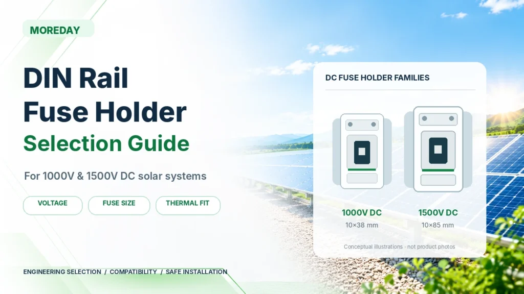
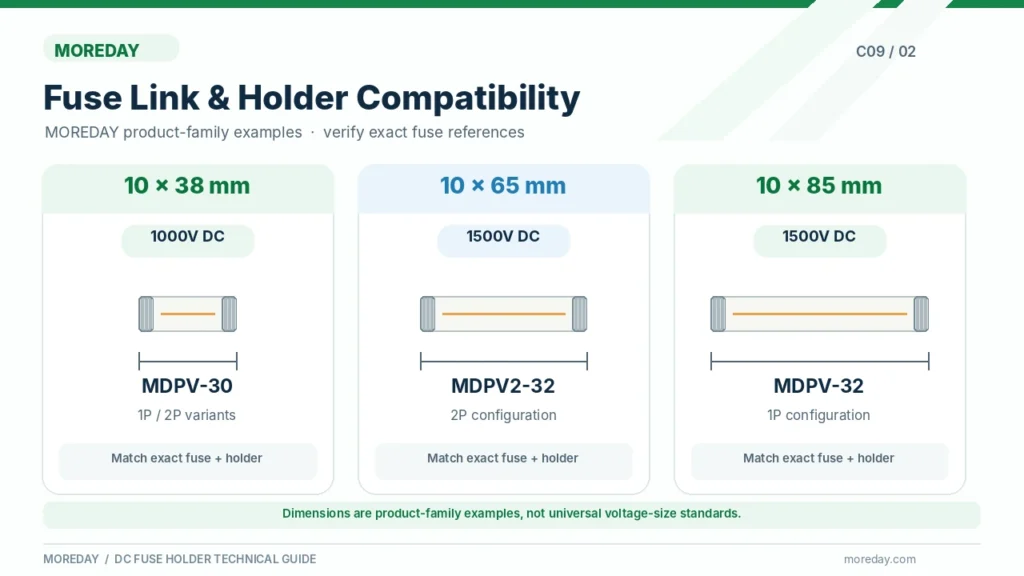
For solar applications, common product options include 1000V and 1500V DC holders designed for cylindrical fuse links such as 10×38 mm, 10×65 mm, and 10×85 mm.
This guide explains seven key selection considerations, compares typical product configurations, and shows how to evaluate MOREDAY DIN rail fuse holders for photovoltaic protection.
What Is a DIN Rail Fuse Holder and Why Does Selection Matter?
A DIN rail fuse holder is an electrical component that mounts on a compatible standardized rail and provides the mechanical and electrical interface for a replaceable fuse link.
Its primary functions include:
- Holding the fuse link securely in position.
- Providing reliable electrical contact with the fuse terminals.
- Connecting the fuse to the external circuit.
- Supporting safe installation within its specified ratings.
- Allowing fuse replacement according to the manufacturer’s instructions.
The fuse link, not the holder itself, performs overcurrent interruption.
When sufficient fault current flows through the fuse element, the element melts and the fuse interrupts the current within its rated capabilities.
The holder must remain electrically and thermally compatible with that operation.
Why Fuse Holder Selection Is Important
An incorrectly selected fuse holder can create problems even when the installed fuse link has the correct current rating.
Potential issues include excessive contact resistance, overheating, mechanical incompatibility, insufficient insulation performance, and unsuitable terminal connections.
For example, a 1500V DC-rated fuse link installed in a holder rated only for 1000V DC does not create a 1500V-rated assembly.
Likewise, a holder that accepts a 25A fuse physically may not be suitable for that fuse’s power dissipation or the installation temperature.
The correct approach is to evaluate the fuse link and fuse holder as a compatible combination.
For a basic explanation of the component’s function, read What Is a Fuse Holder and How Does It Work?.
Choose the Correct DC Voltage Rating: 1000V vs 1500V
The first major selection criterion is the holder’s rated voltage.
A holder used in a DC circuit must have suitable manufacturer-specified DC ratings for the maximum voltage that may occur under the relevant operating and fault conditions.
This is particularly important in photovoltaic systems because PV module voltage varies with temperature.
1000V DC Fuse Holders
A 1000V DC fuse holder may be appropriate for an installation where the maximum applicable DC voltage remains within its specified rating.
For example, consider a solar string with a calculated maximum cold-weather open-circuit voltage of 920V.
A correctly specified 1000V DC holder is a potential choice, provided the fuse link and remaining equipment ratings are also suitable.
MOREDAY’s MDPV-30 1000V DC Fuse Holder is an example of a DIN rail-mounted holder designed for 10×38 mm cylindrical fuse links.
1500V DC Fuse Holders
A 1500V DC fuse holder is intended for higher-voltage applications within its specified ratings.
For example, if a PV string has a calculated maximum voltage of 1180V DC, a 1000V-rated holder is insufficient.
An appropriately rated 1500V holder becomes necessary.
MOREDAY provides the MDPV-32 1500V DC Fuse Holder for 10×85 mm fuse links, as well as other configurations within its product range.
However, using a 1500V holder does not automatically make the entire PV circuit suitable for 1500V.
The fuse link, conductors, connectors, inverter, switching equipment, and other electrical components must also have appropriate ratings.
Can a 1500V Holder Be Used in a 1000V System?
A 1500V DC-rated holder may be used in a lower-voltage circuit when the manufacturer permits the application and the complete assembly meets the required electrical and mechanical conditions.
Nevertheless, a higher voltage rating is not automatically the best choice.
Higher-voltage product families may use different fuse dimensions, contact arrangements, and mounting configurations.
A suitable 1000V holder may be more practical for a 1000V installation when it meets all the applicable requirements.
For a deeper comparison, see 1000V vs 1500V DC Fuses: Ratings, Differences & Selection Guide.
Match the Fuse Holder with the Correct Fuse Link Size
Fuse-link compatibility is one of the most important factors in selecting a DIN rail fuse holder.
Cylindrical fuses are manufactured in several physical formats. The holder must accommodate the specific diameter, length, and terminal configuration of the selected fuse.
Common photovoltaic fuse dimensions include:
- 10×38 mm
- 10×65 mm
- 10×85 mm
- 14×85 mm
These dimensions generally describe the nominal diameter and length of a cylindrical fuse link.
They do not, by themselves, identify the fuse’s voltage rating, current rating, or utilization category.
10×38 mm Fuse Holders
The 10×38 mm format is widely used in compact fuse assemblies.
MOREDAY’s MDPV-30 series is designed for 10×38 mm fuse links and is listed for 1000V DC applications.
This format can help reduce installation space in control panels and solar combiner boxes, provided the selected components meet the required ratings.
10×65 mm Fuse Holders
The 10×65 mm format is used in certain higher-voltage photovoltaic fuse assemblies.
MOREDAY lists the MDPV2-32 series as a 1500V DC, two-pole holder configuration for 10×65 mm fuse links.
This illustrates an important point: not every 1500V DC fuse assembly uses a 10×85 mm fuse.
The manufacturer’s specific product design determines the compatible fuse-link dimensions.
10×85 mm Fuse Holders
The 10×85 mm format is another option used in high-voltage PV protection systems.
MOREDAY’s MDPV-32 series is listed for 1500V DC and 10×85 mm fuse links.
A 10×85 mm fuse should not be installed in a holder intended for 10×38 mm or 10×65 mm fuses.
Differences in dimensions can affect contact engagement, insulation clearances, heat dissipation, and mechanical security.
MOREDAY Fuse Holder Size Comparison
| Product Series | Published DC Voltage | Compatible Fuse Size | Pole Configuration |
|---|---|---|---|
| MDPV-30 | 1000V DC | 10×38 mm | 1P / 2P variants |
| MDPV-30B | 1000V DC | 10×38 mm | 1P with indicator variant |
| MDPV-32 | 1500V DC | 10×85 mm | 1P |
| MDPV2-32 | 1500V DC | 10×65 mm | 2P |
These are examples from MOREDAY’s published product range, not universal size requirements for each voltage class.
The exact model, electrical ratings, and permitted fuse-link combinations must be verified using current technical documentation.
Is Physical Compatibility Enough?
No.
Two fuses may have identical dimensions but different electrical characteristics.
A complete compatibility check should include:
- Rated DC voltage.
- Rated current.
- Fuse-link utilization category.
- Breaking capacity and operating characteristics.
- Fuse power dissipation.
- Holder current and thermal ratings.
- Manufacturer-approved fuse and holder combinations.
For photovoltaic string protection, a suitable gPV fuse link may be required.
A physically compatible general-purpose fuse should not automatically replace a gPV fuse in a circuit requiring PV-specific protection characteristics.
Explore MOREDAY’s DC Fuse Link Range for available cylindrical photovoltaic fuse configurations.
Verify Rated Current, Fuse Characteristics and Thermal Performance
A common selection mistake is treating the fuse holder’s current rating as the rating that should be installed in the circuit.
In reality, the fuse link and holder have different functions and may have different current ratings.
Fuse Link Current vs Holder Current
The fuse link’s rated current is selected according to the circuit’s overcurrent protection requirements.
The holder must be capable of carrying the required current with the compatible fuse installed under the specified operating conditions.
For example, assume an electrical design requires a 25A gPV fuse link.
A holder with a verified current rating of 30A may be a candidate because:
25A ≤ 30A
However, this comparison alone is insufficient.
The holder must also be suitable for the fuse’s power dissipation, the installation environment, and the manufacturer’s permitted configurations.
Fuse-Link Power Dissipation
A fuse link generates heat as electrical current passes through its internal resistance.
That heat can be transferred to the fuse holder, contacts, terminals, and surrounding air.
The relevant thermal requirements include both the fuse link’s power dissipation and the holder’s acceptable power dissipation.
A holder that mechanically accepts a particular fuse may still have insufficient thermal capacity for the intended combination.
The manufacturer’s technical data should therefore identify the permitted operating conditions and any restrictions.
Ambient Temperature and Derating
Solar combiner boxes can experience elevated internal temperatures because of direct sunlight, high ambient temperature, electrical losses, and limited ventilation.
Factors that affect thermal performance include:
- Fuse-link operating current.
- Fuse-link power dissipation.
- Contact resistance.
- Number of closely installed fuse holders.
- Spacing between adjacent devices.
- Enclosure ventilation.
- Ambient temperature.
- Conductor arrangement and terminal conditions.
A holder and fuse combination that operates satisfactorily under reference conditions may require derating in a hotter environment.
The appropriate derating must come from the manufacturer’s published information or verified engineering assessment.
Breaking Capacity Is Not a Holder-Only Specification
Breaking capacity describes the current-interruption capability of a fuse link under specified electrical conditions.
The fuse holder does not independently interrupt an overcurrent fault.
When a product description refers to a breaking capacity such as 20kA or 25kA, engineers must determine whether the value belongs to the fuse link or a specified, verified assembly.
It should not be interpreted as the empty holder’s independent current-interruption capability.
The complete fuse arrangement must satisfy the relevant fault-current and equipment requirements.
Check DIN Rail Mounting, Terminals and Pole Configuration
Electrical ratings are essential, but installation compatibility also affects long-term performance.
DIN Rail Compatibility
Many industrial fuse holders use standardized 35 mm mounting rails.
IEC 60715 defines dimensional and functional requirements for standardized mounting rails used with suitable switchgear, controlgear, and accessories.
Common 35 mm mounting rail profiles include 35×7.5 mm and 35×15 mm.
However, not every DIN rail product supports every rail configuration.
Before installation, check the holder’s compatible rail profile, mounting clips, panel-space requirements, and manufacturer’s installation instructions.
Terminal Connections
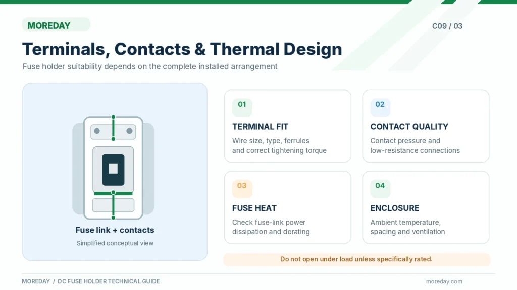
Fuse holder terminals must provide reliable electrical connections to the circuit conductors.
Relevant specifications include:
| Terminal Parameter | Why It Matters |
|---|---|
| Conductor cross-section | Must fit the permitted terminal range |
| Conductor type | Solid and flexible conductors may have different requirements |
| Tightening torque | Required for reliable contact pressure |
| Strip length | Prevents poor connections and exposed conductors |
| Ferrule compatibility | Must follow the manufacturer’s terminal instructions |
| Terminal temperature rating | Affects installation suitability |
| Number of conductors | Must not exceed the terminal’s approved arrangement |
For example, the MOREDAY MDPV-30 product information lists terminals for specified conductor sizes within the 2.5–6 mm² range.
Engineers should confirm the actual terminal specifications for the selected model before determining the cable size or installation method.
Loose or incorrectly terminated conductors can cause excessive contact resistance and overheating.
1P vs 2P Fuse Holders
DIN rail fuse holders are available in different pole configurations.
A single-pole holder provides a fuse position for one conductor.
A two-pole arrangement provides two positions, depending on the manufacturer’s product design.
For photovoltaic applications, the required number of protected conductors depends on the system architecture, earthing arrangement, fault-current paths, and applicable electrical requirements.
A 2P fuse holder must not automatically be assumed to provide a load-break disconnecting function.
Some holders provide two fuse positions without being rated to interrupt load current when opened.
Fuse Indicators
Certain holders incorporate an indicator that helps identify an operated fuse.
This can be useful in control panels and PV combiner boxes containing multiple fuse circuits.
However, a fuse status indicator is not a substitute for electrical isolation or voltage testing.
A PV circuit may remain energized on either side of an operated fuse.
The indicator’s function and limitations should be reviewed in the manufacturer’s documentation.
Safety Requirements and Applicable Standards
DIN rail fuse holders are often installed in electrical systems with hazardous AC or DC voltages.
The correct product must be selected, installed, and maintained according to its ratings and the applicable electrical safety requirements.
Can a DIN Rail Fuse Holder Be Opened Under Load?
Not unless the complete device is specifically rated for the intended switching operation.
A conventional fuse holder is not automatically a load-break switch or an isolator.
Opening a fuse carrier under load can create an electrical arc.
This is particularly important in DC circuits because direct current does not have periodic natural current-zero crossings.
Fuse replacement should be performed only by qualified personnel after the required electrical isolation, lockout/tagout, and verification procedures.
IP Ratings and Outdoor PV Applications
Some DIN rail fuse holders have an IP20 rating under specified conditions.
IP20 does not establish protection against water ingress.
For outdoor solar PV installations, these holders generally need to be installed inside a suitably rated electrical enclosure.
The complete enclosure arrangement must be evaluated for moisture, temperature, solar exposure, and any other relevant environmental conditions.
A product described as a solar fuse holder is not automatically suitable for direct outdoor exposure.
Applicable Technical Standards
| Standard | Relevance |
|---|---|
| IEC 60269-1:2024 | General requirements for applicable low-voltage fuses |
| IEC 60269-6:2010+A1:2021 | Supplementary requirements for photovoltaic fuse links |
| IEC 60715:2017 | Standardized mounting rails |
| UL 4248-1 | General requirements for fuse holders within its defined scope |
These standards address different product characteristics.
IEC 60269-6 is specifically concerned with photovoltaic fuse links. It should not be used as proof that every associated fuse holder has a separate third-party certification.
Similarly, a fuse holder’s reference to IEC standards does not automatically establish UL listing or compliance with the installation requirements of every target market.
For procurement and compliance reviews, obtain documentation identifying the exact product model and applicable ratings.
Signs of Fuse Holder Problems
Warning signs include discolored insulation, damaged fuse carriers, loose terminals, abnormal heating, corroded contacts, and repeated fuse operation.
A damaged holder should not be reused simply because a replacement fuse can still be inserted.
Repeated fuse operation also requires investigation of the underlying circuit conditions before the protective device is replaced.
MOREDAY DIN Rail Fuse Holder Selection Guide
MOREDAY provides DC fuse holders and cylindrical fuse links for photovoltaic protection applications, including 1000V and 1500V product families.
The appropriate selection depends on the complete electrical and installation requirements.
Example A: 1000V PV Combiner Box
Consider a hypothetical installation with the following requirements:
| Parameter | Example |
|---|---|
| Maximum calculated DC voltage | 940V |
| Selected fuse characteristic | gPV |
| Required fuse-link current | 25A |
| Selected fuse-link size | 10×38 mm |
| Installation | DIN rail inside a suitable enclosure |
The MOREDAY MDPV-30 is a potential holder family for evaluation because its published voltage class and supported fuse dimensions align with these preliminary requirements.
However, the actual fuse-link reference, holder current capacity, thermal conditions, terminal arrangement, and compliance documentation must be verified.
Example B: 1500V PV Protection Assembly
Consider another installation requiring:
| Parameter | Example |
|---|---|
| Maximum calculated DC voltage | 1180V |
| Selected fuse characteristic | gPV |
| Fuse-link dimensions | 10×85 mm |
| Required configuration | Single-pole fuse position |
| Installation | DIN rail inside a suitable enclosure |
The MOREDAY MDPV-32 is a possible holder family because it is listed for 1500V DC, 10×85 mm fuse links, and a single-pole configuration.
The final selection still requires model-specific electrical and thermal verification.
If the design instead specifies a 10×65 mm fuse link and a two-pole holder, the MDPV2-32 family may be considered.
These holder series should not be treated as mechanically interchangeable.
MOREDAY Product Comparison
| Model | Published Voltage | Fuse Size | Configuration | Typical Application |
|---|---|---|---|---|
| MDPV-30 | 1000V DC | 10×38 mm | 1P/2P series options | Compact PV protection assemblies |
| MDPV-30B | 1000V DC | 10×38 mm | 1P with indicator option | PV circuits requiring fuse indication |
| MDPV-32 | 1500V DC | 10×85 mm | 1P | Higher-voltage PV fuse protection |
| MDPV2-32 | 1500V DC | 10×65 mm | 2P | Higher-voltage two-pole fuse-holder arrangements |
The table represents published product-family configurations. Exact electrical ratings, compatible fuse models, and available variations should be confirmed before procurement.
DIN Rail Fuse Holder Selection Checklist
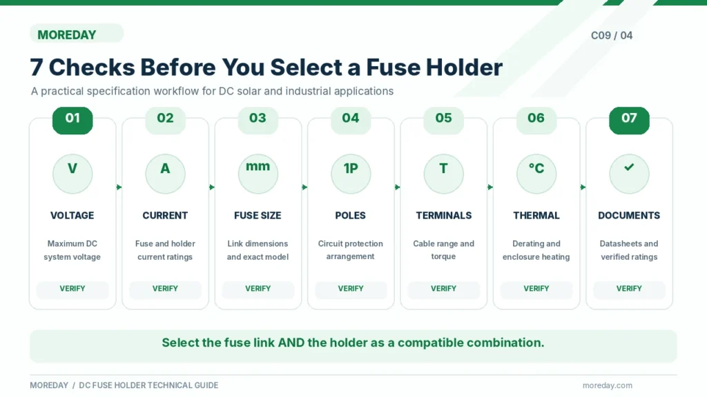
Before placing an order, verify the following:
| Selection Item | Required Information |
|---|---|
| Circuit application | PV string, combiner box, or industrial DC circuit |
| Maximum DC voltage | Calculated system voltage |
| Fuse-link rated current | Established by the protection design |
| Fuse characteristic | gPV or other appropriate category |
| Fuse dimensions | Supported cylindrical fuse-link format |
| Holder current rating | Compatible with the selected fuse and operating conditions |
| Number of poles | Based on the required protection arrangement |
| Conductor terminals | Cable size, type, and installation requirements |
| Thermal conditions | Ambient temperature, spacing, enclosure heating |
| DIN rail | Compatible mounting profile |
| Documentation | Datasheets, drawings, instructions, applicable conformity evidence |
Explore MOREDAY DC Fuse Holder Products
MOREDAY offers fuse holders and links for photovoltaic DC protection applications.
Relevant resources include:
- MOREDAY DC Fuse and Fuse Holder Product Range
- MDPV-30 1000V DC Fuse Holder
- MDPV-32 1500V DC Fuse Holder
- 1000V/1500V DC Fuse Links
For EPC contractors, electrical panel builders, solar equipment distributors, and OEM customers, a technical inquiry should specify the intended circuit, maximum DC voltage, fuse-link current and dimensions, pole configuration, mounting conditions, and required documentation.
This information helps determine the correct combination rather than selecting a holder based only on its advertised voltage class.
Conclusion
A reliable DIN rail fuse holder must match the electrical and installation requirements of the circuit and the fuse link it supports.
The most important selection factors are DC voltage rating, fuse-link dimensions, current and thermal compatibility, pole configuration, terminal connections, and manufacturer documentation.
For solar PV systems, the selected fuse link must also provide the appropriate photovoltaic protection characteristics.
MOREDAY’s 1000V and 1500V DC fuse holder families offer different options for PV protection assemblies, but final selection should always be based on verified model-specific specifications.
Explore MOREDAY DC Fuse Solutions to compare available products and request technical selection support for your project.

