
DistributionSolar
PV string fuses are required when fault currents from parallel strings or other connected sources can exceed the safe overcurrent limits of PV modules, conductors, or associated equipment. A single PV string may not need dedicated overcurrent protection, while an array with several parallel strings may require individual string fuses to protect against reverse-current faults.
However, the number of parallel strings alone does not determine whether fuses are mandatory. The decision depends on the module’s maximum series fuse rating, the available fault current, cable current-carrying capacity, system architecture, and applicable electrical standards.
This guide explains when solar string fuses are necessary, how reverse current develops, and how engineers can evaluate protection requirements under IEC and NEC design frameworks.
Why Do Solar PV Strings Need Overcurrent Protection?
Photovoltaic modules behave differently from conventional electrical power sources.
A PV module is inherently current-limited. Its output current is largely determined by solar irradiance and the electrical characteristics of the module.
Under normal operation, modules connected in series carry approximately the same string current. Connecting several strings in parallel increases the total current available to the combined circuit.
The main concern arises when a fault creates an unintended current path.
How Reverse Current Develops
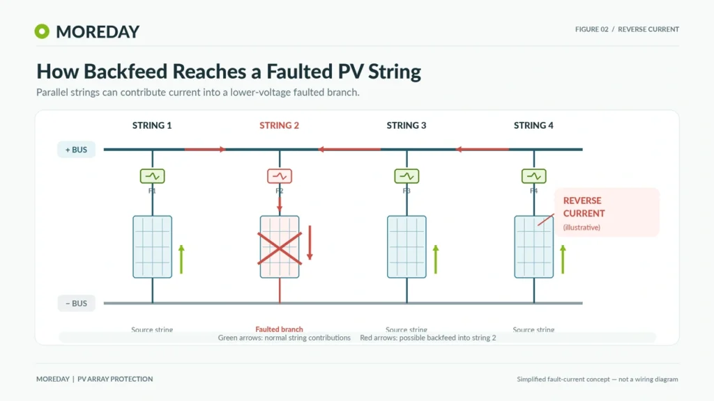
Consider a PV array containing four identical strings connected in parallel.
Under normal conditions, all four strings contribute current toward the inverter or combiner output.
If a fault develops in one string, the remaining three strings may contribute current into the faulted branch, depending on the fault location and circuit conditions.
The current can then flow in the opposite direction through parts of the affected string.
This is known as reverse current or backfeed current.
A simplified sequence is:
Parallel PV strings → Fault in one string → Current contribution from healthy strings → Reverse current in the faulted branch → Potential overheating or damage
The combined reverse current may exceed the affected module’s permitted overcurrent rating or the current-carrying capacity of its conductors.
Appropriate overcurrent protection can limit the duration of a qualifying fault current.
What Does a String Fuse Protect?
A correctly specified PV string fuse can help protect:
- PV modules against excessive reverse-current conditions.
- String conductors against overcurrent caused by other connected sources.
- Associated circuit components within the protection limits established by the design.
The fuse is not a universal safety device.
It does not replace ground-fault detection, arc-fault protection, surge protection, or appropriately rated disconnecting equipment where those functions are required.
It also cannot be assumed to interrupt every possible electrical fault. Some PV faults produce insufficient current to operate a fuse within the required time.
Do Single and Two Parallel Solar Strings Need Fuses?
Not every PV installation requires a dedicated fuse for each string.
The number of strings provides a useful starting point, but the final requirement depends on the complete electrical arrangement.
Single PV String
A standalone PV string contains modules connected in series without parallel strings supplying current into it.
Where the PV string is the only source and no inverter, battery, or other connected equipment can supply additional fault current, the string’s available current is inherently limited.
If the conductors and equipment are adequately rated for that current, dedicated string overcurrent protection may not be necessary.
For example, consider one string containing 16 identical solar modules.
If the string has no external backfeed source, an internal short-circuit fault does not normally create the same high reverse-current risk found in large parallel arrays.
However, the absence of a string fuse does not eliminate the need for other required electrical protection or isolation provisions.
Two Parallel PV Strings
When two identical strings are connected in parallel, a fault in one string may receive current from the other string.
For a simplified initial assessment, assume each string has a short-circuit current of 13A at Standard Test Conditions (STC).
If one string develops a fault, the remaining healthy string may contribute approximately 13A under the simplified model.
Suppose the affected modules have a maximum series fuse rating of 25A.
The estimated reverse-current contribution is below that rating:
13A < 25A
This suggests that dedicated string fuses might not be required for module reverse-current protection in this example.
However, the conclusion remains conditional.
The design must also verify the current-carrying capacity of the conductors, relevant irradiance and temperature conditions, any other connected sources, and the applicable installation rules.
Two parallel strings are not automatically exempt from overcurrent protection.
What About Three Parallel Strings?
Three parallel strings require more careful evaluation because a faulted string may receive contributions from two healthy strings.
If each healthy string contributes approximately 13A at STC, the total estimated reverse current could reach:
2 × 13A = 26A
If the module’s maximum series fuse rating is 25A, the estimated reverse current exceeds that limit.
This is a strong indication that string overcurrent protection is required unless the complete design demonstrates an acceptable alternative under the governing rules.
The important distinction is that the protection decision comes from the available fault current and equipment limits—not simply from counting three strings.
How Does the Number of Parallel Strings Affect Fuse Requirements?
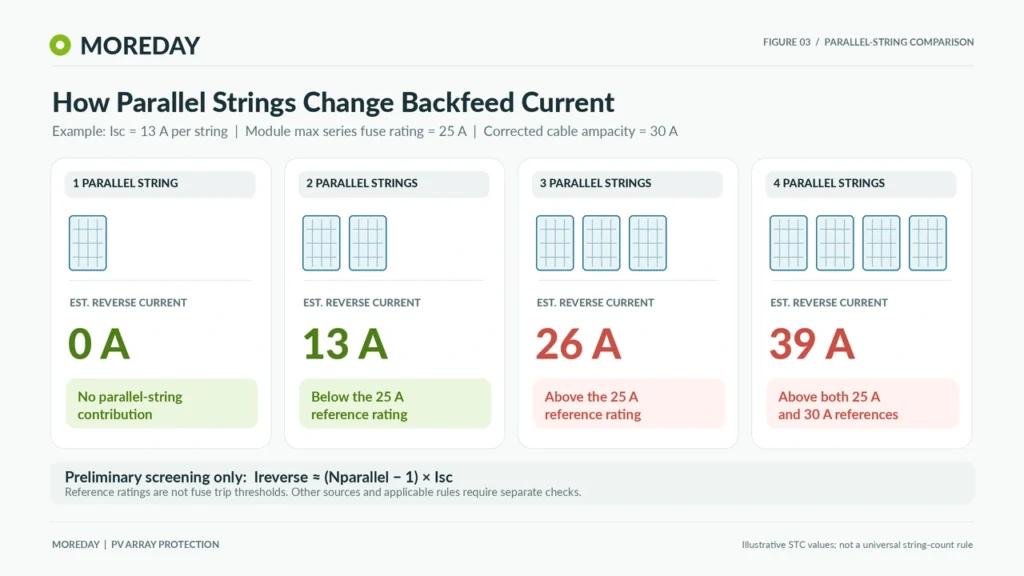
As more PV strings are connected in parallel, the potential current contribution to a faulted string increases.
For a preliminary assessment involving identical strings, the reverse-current contribution from the remaining healthy strings can be approximated by:
Ireverse ≈ (Np − 1) × Isc
Where:
- Ireverse = estimated current contribution from healthy parallel strings.
- Np = total number of parallel strings.
- Isc = short-circuit current of one string at STC.
This equation is a simplified screening tool, not a complete design calculation. Actual fault current depends on irradiance, module characteristics, circuit conditions, connected electronic equipment, and other possible current sources.
Example: One to Four Parallel Strings
Assume the following hypothetical PV module specifications:
| Parameter | Value |
|---|---|
| Module short-circuit current (Isc) | 13A |
| Module maximum series fuse rating | 25A |
| Corrected string cable ampacity | 30A |
| Additional backfeed sources | None assumed |
Using the simplified reverse-current relationship:
| Parallel Strings | Estimated Reverse Current | Preliminary Assessment |
|---|---|---|
| 1 | 0A from other strings | String fuse may be unnecessary |
| 2 | 13A | Below the stated module and cable limits |
| 3 | 26A | Exceeds the 25A module limit; protection needs attention |
| 4 | 39A | Exceeds both the 25A module limit and 30A cable ampacity |
The example demonstrates how the protection requirement can change even when identical modules and cables are used.
For the three-string configuration, the module overcurrent limit becomes important.
For the four-string configuration, both module protection and conductor protection require attention.
Why This Is Only a Preliminary Assessment
A real design must consider current under conditions beyond STC.
For example, module short-circuit current can increase when irradiance exceeds 1000 W/m². Bifacial modules and non-optimal orientations can introduce additional considerations under the applicable IEC design method.
The final calculation may therefore use adjusted current values rather than simply multiplying the nameplate Isc.
The simplified example also assumes that no other equipment can contribute fault current.
A hybrid inverter, battery-connected DC circuit, or another source could change the analysis significantly.
Does Every Array with Three or More Strings Require Fuses?
No universal three-string rule applies to every PV installation.
Some appropriately designed three-string configurations may satisfy the relevant overcurrent protection requirements without individual string fuses.
Others may require them because the potential reverse current exceeds the module manufacturer’s limits or the protected conductors’ permissible current.
The correct assessment must consider the entire system and the adopted electrical standard.
How to Determine Whether String Fuses Are Required
Engineers can assess string fuse requirements using a structured decision process.
Step 1: Identify All Possible Current Sources
Start by identifying every source that can supply current into the circuit under normal or fault conditions.
These may include:
- Other parallel PV strings.
- Parallel sub-arrays.
- Energy storage equipment connected through an arrangement capable of supplying backfeed current.
- Power conversion equipment capable of contributing fault current.
The current sources depend on the actual system topology. An ordinary grid-connected inverter should not automatically be assumed to contribute a substantial DC backfeed current.
Step 2: Identify the Module’s Overcurrent Protection Limit
Find the maximum series fuse rating or maximum overcurrent protection rating in the PV module datasheet.
This value represents a critical limit for the module protection assessment.
For example, a module datasheet might specify:
- Isc: 13A
- Maximum series fuse rating: 25A
The 25A value is not an instruction to install a 25A fuse in every arrangement.
It is a limit that must be considered if an overcurrent protective device is needed.
Step 3: Evaluate the Available Fault Current
Determine the maximum relevant current that could flow into a faulted string.
For parallel arrays, include the contributions from other strings and any additional applicable sources.
Use the calculation method required by the project’s electrical standard, including the appropriate current adjustment factors.
If the available current can exceed the permitted module or equipment limits, additional protection is required unless an accepted alternative design removes the risk.
Step 4: Verify Cable Current-Carrying Capacity
The string conductors must also withstand the expected current under the relevant conditions.
Cable ampacity can be affected by:
- Ambient temperature.
- Installation method.
- Cable grouping.
- Conductor insulation ratings.
- Terminal temperature limitations.
- Other applicable correction and adjustment factors.
A module may be adequately protected while the conductor remains undersized for the available fault current.
Conversely, selecting a larger cable does not automatically eliminate the module’s need for overcurrent protection.
Step 5: Apply the Relevant Electrical Standard
Once the fault currents and equipment limits are understood, evaluate the design against the applicable standard.
For IEC-oriented projects, IEC 62548-1 addresses PV array design, including overcurrent protection.
For U.S. projects, Article 690 of the National Electrical Code is particularly important.
The applicable edition and local amendments must be confirmed before making the final determination.
Step 6: Document the Protection Decision
A well-documented engineering design should record:
- The number of series modules and parallel strings.
- Module datasheet and maximum overcurrent protection rating.
- Calculated fault-current contributions.
- Corrected conductor ampacities.
- Applicable standards and design assumptions.
- The selected protective device, where required.
- Any equipment-specific exceptions or alternative protection methods.
This documentation is useful for engineering reviews, installation inspections, and future system maintenance.
Where Should PV String Fuses Be Installed?
When string fuses are required, their placement should correspond to the source of the hazardous overcurrent and the circuit being protected.
In many PV systems, string fuses are installed inside a DC combiner box where the individual string conductors connect to common busbars.
String Fuses Inside Solar Combiner Boxes
A solar DC combiner box combines several PV strings into a common output circuit.
Depending on the design, it may contain individual fuse links and holders for string protection.
The basic arrangement is:
Individual PV strings → String protection devices → Common DC busbars → PV array output → Inverter
The string fuses are selected to interrupt qualifying fault currents contributed through the parallel connection.
However, a combiner box does not necessarily require a fuse on every input if the design establishes that overcurrent protection is unnecessary under the applicable rules.
The enclosure’s protection arrangement must match the actual system configuration.
Positive and Negative Conductor Protection
The required number and location of protective devices depend on the system’s earthing arrangement, current paths, and governing standard.
Some PV installations use overcurrent protective devices in both positive and negative conductors.
In other configurations, a protective device in one appropriate conductor may be permitted when the necessary conditions are satisfied.
Neither arrangement should be specified universally without reviewing the electrical design.
Engineers must also consider the requirements for grounded and ungrounded conductors, fault detection, and isolation.
Can an Inline Fuse Connector Replace a Combiner Box Fuse?
An inline PV fuse assembly may be an option for particular system designs.
However, its suitability depends on more than connector appearance or fuse ampere rating.
It must have suitable PV/DC ratings, compatible mating interfaces, environmental protection, and the required product documentation.
Its placement must also satisfy the electrical protection requirements of the circuit.
An inline fuse should not be treated as automatically interchangeable with a fuse assembly in a combiner box.
Are Blocking Diodes or Surge Protectors Alternatives?
Bypass diodes within PV modules and blocking diodes used in certain array configurations perform functions different from overcurrent protective devices.
A blocking diode may reduce reverse-current flow under specified conditions, but it is not a general substitute for required fuse protection.
Similarly, a DC surge protective device (SPD) is intended to limit transient overvoltages.
An SPD does not replace a required string fuse, and a string fuse does not replace an SPD.
IEC and NEC Requirements for PV String Overcurrent Protection
PV string protection must be evaluated against the requirements applicable to the installation location.
Although IEC and NEC frameworks share many safety objectives, their detailed calculation methods and equipment requirements are not identical.
IEC 62548-1: PV Array Design Requirements
IEC 62548-1:2023+A1:2025 addresses photovoltaic array design, including DC wiring, protection devices, switching, and earthing provisions.
Its overcurrent protection provisions consider potential current contributions under fault conditions and the permitted limits of the protected equipment.
The standard also addresses installations that incorporate DC conditioning units and other system architectures that can change the fault-current assessment.
Therefore, the same simplified calculation should not be applied indiscriminately to conventional strings, optimizer-based systems, and battery-connected installations.
IEC 60269-6: Fuse Links for PV Protection
IEC 60269-6:2010+A1:2021 specifies supplementary requirements for fuse links intended for solar photovoltaic protection applications.
It provides the technical basis for PV fuse-link characteristics, including devices commonly identified by the gPV utilization category.
PV circuits can produce comparatively low fault-current multiples. Suitable PV fuse characteristics are important because a general-purpose DC fuse may not provide the required protection in the relevant fault-current range.
IEC 60269-6 is a fuse-link product standard, not a substitute for the system-level protection assessment under IEC 62548-1.
NEC Article 690: U.S. Photovoltaic Protection Requirements
In the United States, NEC Article 690 addresses photovoltaic electrical installations.
Section 690.9 provides requirements for overcurrent protection, including conditions under which certain PV circuits may not require separate overcurrent protective devices.
A central consideration is whether the conductors have adequate ampacity and whether currents from all applicable sources remain within the relevant equipment limits.
The adopted NEC edition, local amendments, listed equipment instructions, and the Authority Having Jurisdiction (AHJ) must be consulted.
For additional background, the University of Maryland Extension’s solar wiring and fusing guide discusses source circuits, parallel strings, and overcurrent protection using the 2023 NEC framework.
Manufacturer Application Guides
Fuse manufacturers also provide application-specific recommendations.
For example, Eaton’s photovoltaic fuse application guide explains the relationship between parallel strings, cable ratings, fuse characteristics, and environmental derating.
Such guides are useful engineering resources, but their recommendations should be distinguished from the mandatory provisions of the adopted electrical code.
PV String Protection Checklist and MOREDAY Fuse Solutions
Before specifying PV string fuses, verify the following information.
| Design Question | Required Check |
|---|---|
| How many strings are connected in parallel? | Confirm array topology |
| Can other circuits supply reverse current? | Identify all relevant backfeed sources |
| What is the maximum possible fault current? | Apply the appropriate calculation method |
| What is the module protection limit? | Check maximum series fuse rating |
| Are the cables adequately rated? | Verify corrected conductor ampacity |
| Are string fuses required? | Apply the governing IEC/NEC provisions |
| Which fuse characteristic is appropriate? | Confirm gPV or other specified PV-rated protection |
| Where should the fuses be installed? | Review fault-current paths, polarity and earthing |
| Are the fuse links and holders compatible? | Verify ratings, dimensions and manufacturer documentation |
Selecting the Appropriate PV Fuse Components
If the assessment establishes a need for string overcurrent protection, the selected fuse link must have appropriate DC voltage, current, breaking capacity, and operating characteristics.
The fuse holder must also be compatible with the selected fuse link and installation conditions.
MOREDAY offers photovoltaic protection components including:
- DC Fuse Links for 1000V and 1500V Systems
- MDPV-30 1000V DC Fuse Holder
- MDPV-32 1500V DC Fuse Holder
- Solar DC Combiner Box Solutions
Product selection should be based on the actual circuit parameters and verified model-specific technical documents.
A 1000V or 1500V marking alone does not demonstrate that the fuse assembly is suitable for every PV installation operating at that voltage.
Engineering and Procurement Support
For EPC contractors, system integrators, distributors, and OEM customers, providing complete project information helps avoid incorrect protective device selection.
Useful information includes the PV module datasheet, string configuration, maximum system voltage, expected fault currents, installation environment, and applicable standards.
MOREDAY’s DC Fuse Product Range provides a starting point for identifying available fuse links, holders, and related PV protection solutions.
Conclusion
PV string fuses are necessary when the available fault current can exceed the limits of PV modules, conductors, or other protected equipment and the applicable design rules require overcurrent protection.
A standalone PV string may not require a dedicated fuse, while arrays with several parallel strings are more likely to need individual string protection because of the potential for reverse-current faults.
The deciding factors are the actual fault-current paths, equipment limits, and governing electrical standards—not a fixed number of solar panels or strings.
Properly assessing these requirements helps engineers select appropriate PV protection and avoid both unnecessary equipment and insufficient fault protection.