DistributionSolar
DC MCB trip curves are the single most misunderstood parameter in solar PV and battery system design. Most installers know to pick a “C-curve for solar” — but ask them why, or what happens if they use a B-curve instead, and the answer gets fuzzy fast. That vagueness leads to two real problems: nuisance tripping that disrupts system output, and — far worse — breakers that hold when they should interrupt.
This guide goes beyond the label. We’ll explain what DC MCB trip curves actually govern, why DC systems have stricter requirements than their AC equivalents, and how to choose between Type B, C, and D for every major application in renewable energy and energy storage.
What a Trip Curve Actually Controls
Before comparing DC MCB trip curves B, C, and D, it’s worth being precise about what a trip curve is and isn’t.
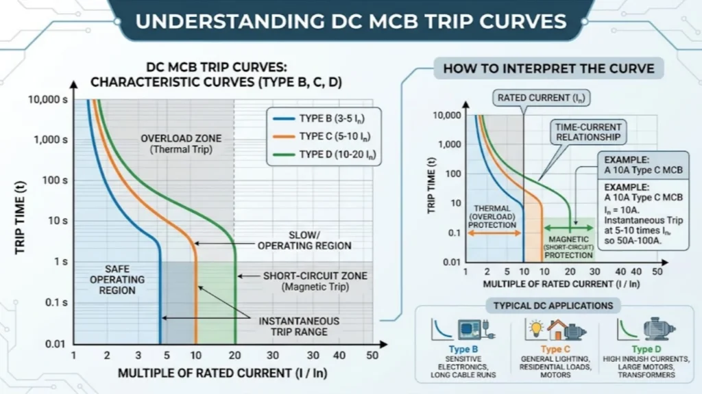
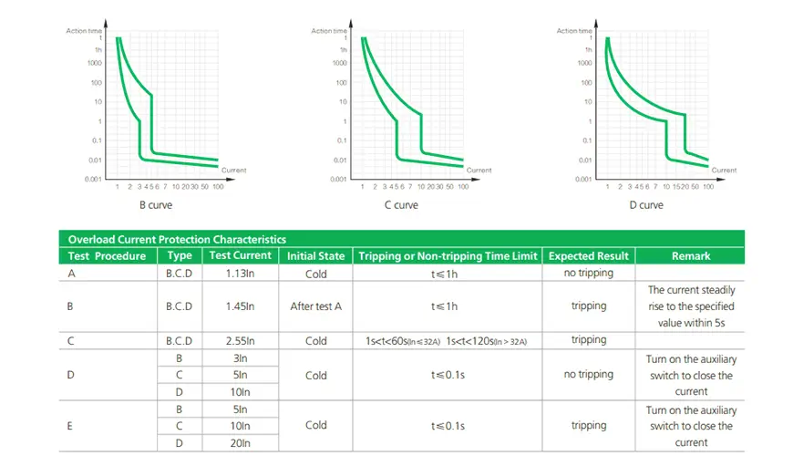
A trip curve is a graph — defined by IEC 60898-3 for DC applications — that plots the relationship between overcurrent magnitude (expressed as a multiple of the breaker’s rated current, In) and the time the breaker will take to open. It does not describe a single threshold. It describes a band of behaviour across two distinct protection mechanisms working in parallel inside every MCB:
Thermal trip (bimetallic strip): Responds to sustained overloads — current that exceeds In for an extended period. The bimetallic strip heats up proportionally to I²t, bends, and eventually releases the trip mechanism. This is a slow process by design, measured in seconds to minutes. It protects cables from heat damage caused by prolonged excess current.
Magnetic trip (electromagnetic release): Responds to sudden, large fault currents — short circuits and severe overcurrents. When current spikes beyond a set multiple of In, the magnetic field in the solenoid is strong enough to mechanically actuate the trip instantly, in milliseconds. This protects against short circuits and catastrophic faults.
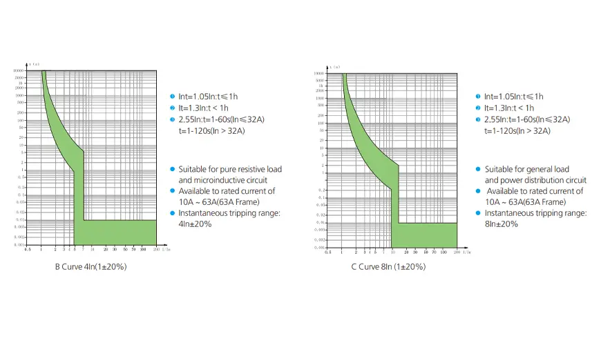
The trip curve defines the magnetic trip threshold — the multiple of In at which the magnetic release fires. The thermal element is consistent across B, C, and D curves. What differs is purely the instantaneous magnetic trip range:
- Type B: Magnetic trip at 3–5× In
- Type C: Magnetic trip at 5–10× In
- Type D: Magnetic trip at 10–20× In
This means a C-curve MCB will ride through a momentary current spike of up to 9× its rated current without tripping magnetically. A B-curve MCB would have already opened at 4× In. A D-curve MCB won’t respond magnetically until the current reaches at least 10× In.
Why DC Systems Demand More Careful Curve Selection
In an AC system, the current naturally crosses zero 100 or 120 times per second (at 50 Hz and 60 Hz respectively). When a breaker opens, the arc between the separating contacts is extinguished at one of these zero crossings — a natural reset that limits arc energy.
In a DC system, there is no zero crossing. Once an arc forms between opening contacts, it is self-sustaining as long as the circuit voltage exceeds the arc voltage. DC MCBs use arc splitter plates and magnetic blowout systems to force extinction artificially — but the arc energy and the time taken to extinguish it are both higher than in equivalent AC interruptions.
This has two practical consequences for trip curve selection:
1. Nuisance tripping is more disruptive in DC systems. In a solar PV string, a nuisance trip disconnects the entire string from the combiner — potentially for hours if the site is unattended. Every unwanted trip is lost generation. Choosing a curve that is too sensitive (B-curve on an inverter circuit) means repeated false disconnections every time the inverter starts or a cloud passes.
2. The “edge-of-cloud” effect. When a dense cloud clears rapidly, the irradiance on a PV array can spike from near-zero to near-peak in under a second. This causes a sharp, brief current surge on every string — not a fault, but a genuine current spike that can reach 1.2–1.3× the string’s short-circuit current for a fraction of a second. A B-curve MCB at the sensitivity end of its magnetic range may respond to this as a fault. A C-curve will ride through it without interruption.
These two factors — sustained DC arcs and real-world current transients in solar systems — are why the industry default for DC PV string protection is C-curve, not B-curve. But that’s not the whole picture.
Type B: When Sensitivity Is the Priority
Type B is the most sensitive of the three DC MCB trip curves, opening under magnetic trip conditions at 3–5× rated current.
Type B is the most sensitive of the three curves. It opens under magnetic trip conditions at a relatively low multiple of rated current, which means it responds quickly to fault conditions but also reacts to inrush currents that other curves would ignore.
Where Type B belongs in DC systems:
- DC control circuits and signal wiring: Logic panels, monitoring equipment, and sensor circuits typically have very low inrush currents and no significant load-switching transients. A Type B provides tight protection without any risk of nuisance tripping.
- DC lighting circuits: LED drivers, once running, draw near-constant current with minimal startup surge. Type B protection is appropriate and provides faster fault response.
- PV systems with very short string cables: In installations where the cable runs between panels and the combiner box are short, the cable itself has low impedance. A short-circuit fault generates a very high fault current almost instantly — the high fault current means even a B-curve MCB’s instantaneous threshold is well exceeded, so the sensitivity advantage of B-curve doesn’t create nuisance trips. However, this is a niche case; most practical installations benefit from C-curve for the reasons described above.
- Battery storage sub-circuits: Low-current control and monitoring outputs from a BMS can be appropriately protected by B-curve MCBs at the sub-circuit level.
Where Type B does NOT belong:
- PV string protection (inverter inrush and edge-of-cloud effects will cause nuisance trips)
- Any circuit with capacitive or inductive load switching
- DC motor drive input circuits
Type C: The DC System Standard
Type C is the most widely deployed DC MCB trip curve in renewable energy systems, and for good reason.
Type C is the most widely deployed curve in DC renewable energy systems, and for good reason. Its magnetic trip range is wide enough to accommodate the startup transients and irradiance-driven current spikes typical of solar and battery applications, while remaining sensitive enough to respond reliably to genuine fault currents.
Where Type C belongs in DC systems:
PV string protection in combiner boxes. This is Type C’s home territory. A solar string’s short-circuit current (Isc) is relatively consistent and well-characterised — typically 5–10% higher than its maximum power current (Impp). The edge-of-cloud spike, inverter startup, and panel mismatch effects all produce transients well within the 5–10× window that C-curve will tolerate without tripping. When a genuine fault occurs — a cable insulation failure, a ground fault, a short in a junction box — the fault current will typically exceed 10× In on a well-designed string, well above the C-curve magnetic trip threshold.
Battery main disconnect circuits. Lithium-ion and LFP battery banks exhibit a characteristic called the “pulse current” behaviour — brief, high-current demands from loads like inverters initiating a discharge. These pulses can reach 3–5× the sustained rated current for fractions of a second. A B-curve MCB would respond to these pulses as potential faults; a C-curve rides through them correctly.
Inverter DC input disconnect. The input stage of a grid-tied or hybrid inverter draws startup current during its DC-link capacitor charging phase. This inrush, while brief, can reach 3–8× the sustained operating current. C-curve is the correct choice for this protection point.
EV charging station DC bus protection. DC fast charger rectifier outputs operate at varying current profiles depending on the vehicle’s state of charge and negotiated charge rate. Current transitions can be sharp, particularly when a new charging session begins. C-curve provides the tolerance needed without compromising fault protection.

Type D: For High-Inrush Loads
Type D is the highest-inrush-tolerance DC MCB trip curve in standard IEC classification.
Type D is the highest-inrush-tolerance curve in standard IEC classification. It is designed for loads whose startup current is dramatically higher than their running current — typically 10–15× or more — for a brief but definite period.
Where Type D belongs in DC systems:
- DC motor drives and compressors: Large DC motors, including those used in industrial HVAC, pumping stations, or DC-fed variable frequency drives, can draw 10–15× rated current during startup before back-EMF develops. Type D is the correct protection for these motor circuits.
- Transformer primary circuits (DC-fed): Switch-mode transformers and DC/DC converters with large input filter capacitors exhibit significant inrush current at energisation. Type D provides the tolerance required without nuisance tripping.
- Large inverter inputs in utility-scale systems: In very large central inverter installations with significant DC link capacitance, startup inrush can exceed the C-curve’s magnetic threshold. D-curve MCBs at the feeder level — upstream of C-curve string breakers — support better protection coordination while accommodating startup conditions.
What to watch with Type D:
The wide magnetic trip window (10–20× In) means Type D MCBs require a higher fault current to trip instantaneously. In circuits with high cable impedance (long cable runs, small conductors), the available fault current at the MCB terminals during a short-circuit event may not be sufficient to guarantee magnetic trip within the required time limit. This is the “minimum short-circuit current” problem: always verify that the prospective fault current at the furthest point of the circuit exceeds 1.25× the minimum magnetic trip threshold of the selected curve.
Protection Coordination: The System-Level View
Choosing the right curve for a single device is only part of the job. In a multi-tier protection system — strings → combiner → main disconnect — the trip curves at each level must be coordinated so that the device closest to the fault trips first, leaving the rest of the system running.
This is called selective coordination, and it has a direct rule: the upstream device must have a higher magnetic trip threshold (or a time-delayed trip) compared to the downstream device at every fault current level.
A practical example in a solar PV combiner:
| Protection tier | Device | Recommended curve | Magnetic trip threshold |
|---|---|---|---|
| PV string (input to combiner) | DC MCB, 20A | C-curve | 100–200A |
| Combiner output (to inverter) | DC MCCB, 200A | Adjustable, set high | >1000A |
| Inverter DC input disconnect | DC MCCB, 200A | Adjustable electronic | Time-delayed |
If all three levels used C-curve MCBs without coordination, a string fault could trip both the string breaker and the combiner output breaker simultaneously — taking down the entire array rather than just the affected string. Proper curve selection at each level, with the upstream threshold meaningfully higher than the downstream, ensures only the string breaker opens on a string fault.
The coordination rule in practice: Use C-curve MCBs at the string level (lowest tier). Set upstream MCCBs to trip magnetically at a multiple that is at least 1.5× the maximum prospective fault current seen by the string-level breakers. This creates a clear separation between tiers and guarantees selectivity.
DC MCB Trip Curves B, C and D: Quick Reference by Application
| Application | Load characteristic | Inrush level | Recommended curve |
|---|---|---|---|
| PV string protection | Resistive/capacitive source | Low-moderate (edge-of-cloud) | C |
| Inverter DC input | Capacitive inrush at startup | Moderate (3–8× In) | C |
| Battery main disconnect | Pulse discharge, BMS switching | Moderate (3–5× In) | C |
| DC control circuits | Resistive, constant | Minimal | B |
| DC LED lighting | Near-resistive | Minimal | B |
| DC motor circuits | High-inrush rotating machines | High (10–15× In) | D |
| DC/DC converter input | Capacitive filter inrush | High (10–15× In) | D |
| Utility-scale feeder (main) | Upstream aggregation | Varies | D or electronic MCCB |
Sizing the Rated Current: The 125% Rule and Temperature Derating
Selecting the correct trip curve is only meaningful if the rated current (In) is correctly sized first. Two adjustments are always required:
The 125% continuous duty factor (NEC 690.9 / IEC 60364-7-712): Solar PV strings are defined as continuous sources — current flows for more than three hours at a time. For continuous duty, the minimum rated current of the protective device must be at least 125% of the maximum string current:
MCB minimum In = Isc × 1.25
For a string with an Isc of 10A, the minimum MCB rating is 12.5A — meaning you would select a 16A MCB as the next standard size.
Temperature derating: Standard DC MCBs are calibrated at 40°C ambient. In rooftop combiner boxes, enclosures in direct sun, or desert installations, ambient temperatures frequently exceed 50–60°C. For every 10°C above the calibration temperature, the effective current-carrying capacity of the MCB drops by approximately 10–15%. Failure to account for this leads to chronic thermal tripping under full-sun conditions — not a fault, just an undersized device operating beyond its thermal comfort zone.
Derated In = Required In ÷ Derating factor
At 60°C with a 0.85 derating factor, a circuit requiring 16A sustained needs a MCB rated at 16 ÷ 0.85 ≈ 19A — select a 20A device.
Always apply both corrections before selecting a rated current, then apply the trip curve selection on top.
Common Mistakes and How to Avoid Them
Using B-curve on PV string circuits. The edge-of-cloud effect and inverter startup will cause repeated nuisance trips. The system appears to work in stable weather and fails intermittently on partly cloudy days — a frustrating fault to diagnose.
Assuming C-curve is always right. For DC motor loads or large converter inputs, C-curve’s 5–10× magnetic threshold may be tripped by startup inrush — every time the motor starts. The solution is D-curve, not a larger C-curve MCB.
Ignoring coordination between tiers. String breakers and combiner breakers with matching curves will race each other to trip on a fault. The result is unpredictable system behaviour and difficult fault isolation. Design coordination into the system from the beginning, not as an afterthought.
Not verifying minimum fault current for D-curve devices. In long cable runs, the fault current at the end of the cable may not be sufficient to guarantee magnetic trip of a D-curve MCB within the required disconnection time. Calculate Ikmin at the furthest point and verify it exceeds 1.25× the D-curve minimum magnetic threshold.
Summary
DC MCB trip curves B, C, and D describe the magnetic instantaneous trip threshold — the multiple of rated current at which the breaker opens in milliseconds. In DC systems, where arc extinction is more demanding and load transients are real, curve selection matters more than in AC applications.
For the majority of solar PV and battery storage applications, C-curve is the correct default for string-level and inverter-input protection. B-curve belongs on control circuits and lighting where inrush currents are minimal. D-curve is reserved for motor loads, converter inputs, and upstream feeder positions in coordinated multi-tier systems.
Get the rated current sizing right first (125% rule + temperature derating), then select the trip curve based on the load characteristic and your coordination strategy. These two decisions together determine whether your protection system works as intended — or merely looks like it does.
For a full overview of DC protection principles, including arc extinguishing, breaking capacity, and device standards, see our DC Circuit Breaker: All You Need to Know guide. For device comparisons, see DC MCB vs DC MCCB: What’s the Difference and How to Choose.
External reference: IEC 60898-3 — Circuit-breakers for overcurrent protection for household and similar installations, Part 3: Circuit-breakers for DC operation (iec.ch)