DistributionEnergy Storage
DC circuit breaker for battery energy storage selection is more demanding than for solar PV — and the consequences of getting it wrong are more severe. A miswired PV string loses generation. A fault in a battery energy storage system (BESS) with inadequate protection can release enormous energy in milliseconds, with fire and thermal runaway as the worst-case outcomes.
The challenge is that BESS protection sits at the intersection of several engineering disciplines: electrochemistry, power electronics, protection coordination, and increasingly, code compliance across multiple international standards. This guide pulls those threads together into a single, practical framework for selecting and applying DC circuit breakers across every protection tier in a BESS — from individual cell strings through to the main grid interface disconnect.
Why BESS Protection Is Fundamentally Different From PV Protection
Before diving into device selection, it’s worth being precise about what makes battery energy storage protection a different engineering problem from solar PV protection.
Batteries are not current-limited sources. A PV module cannot supply more than its Isc regardless of the fault impedance. A lithium battery bank has no such natural ceiling. Its internal impedance is extremely low — often milliohms for a large bank — meaning a dead short at the battery terminals can produce fault currents of tens of kiloamps instantaneously. The protective device must be capable of interrupting this current, not merely rated for the normal operating current.
Current flows in both directions. During discharge, current flows from the battery to the load. During charging, it flows from the charger into the battery. DC circuit breakers designed for unidirectional flow use permanent magnets to assist arc extinction — those magnets work in one polarity only. In a BESS, a polarized breaker will fail to extinguish the arc under fault conditions during the charging cycle. Every DC circuit breaker in a BESS application must be explicitly rated as non-polarized and bidirectional.
The voltage range varies with state of charge. Unlike a PV string, whose voltage is determined by module count and temperature, a battery bank’s voltage changes continuously with its state of charge. A 48V nominal LFP bank may sit anywhere from 44V to 58V depending on whether it is near empty or fully charged. A 1000V nominal high-voltage BESS can swing by 200V or more across its operating range. The DC circuit breaker must be rated for the maximum voltage the bank can reach — not the nominal voltage on the system label.
Fault energy is enormous. The energy available in a large BESS during a fault is orders of magnitude greater than in a PV string. A 500 kWh BESS can deliver fault currents exceeding 50 kA from a bank with low internal impedance. The arc energy produced at this fault level is substantial — the DC circuit breaker must not only interrupt the fault current but do so without catastrophic internal failure.
BESS Protection Architecture: The Four Tiers
Effective DC circuit breaker protection in a BESS is never a single device. It is a layered architecture, with each tier serving a different protection function and requiring different device characteristics.
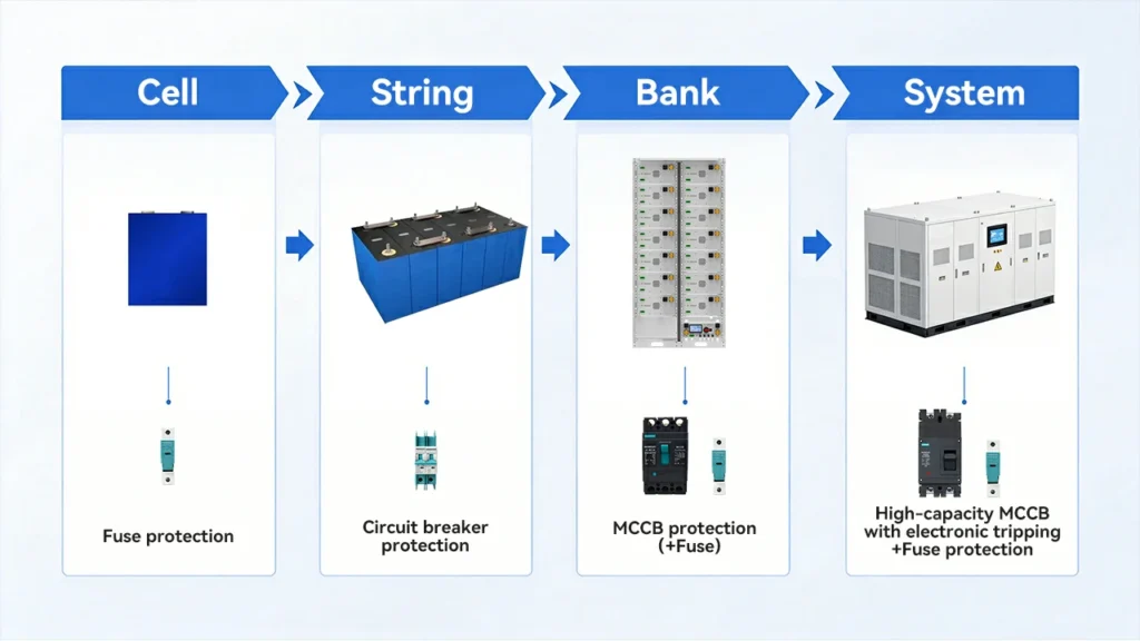
Tier 1 — Cell and Module Level
At the individual cell or module level, protection is typically provided by fuses rather than circuit breakers — fast-acting DC fuses that respond to overcurrent in microseconds, faster than any mechanical breaker can operate. The role of this tier is to protect individual cells from damage due to internal short circuits or severe cell imbalance.
DC circuit breakers are not typically specified at this tier. Understanding this is important: the BMS (Battery Management System) handles cell-level monitoring, but the physical fault protection at this scale belongs to fuses.
Tier 2 — String Level (Rack or Module String)
This is where DC circuit breakers enter the BESS protection scheme. Each battery string — a series-connected group of modules forming one segment of the total bank voltage — should have its own DC circuit breaker at the string output.
Function: Isolates a faulted or underperforming string without disconnecting the entire battery bank. Allows maintenance on individual strings while the rest of the system remains operational. Provides overcurrent protection for the string cabling.
Device requirements:
- Current rating: string continuous discharge current × 1.25, derated for enclosure temperature
- Voltage rating: ≥ maximum string open-circuit voltage (fully charged, worst-case cell imbalance)
- Breaking capacity: must exceed the prospective fault current from parallel strings feeding a fault on the protected string. With N strings in parallel, the maximum reverse current into a faulted string is approximately (N−1) × Isc_string
- Non-polarized: mandatory for bidirectional operation
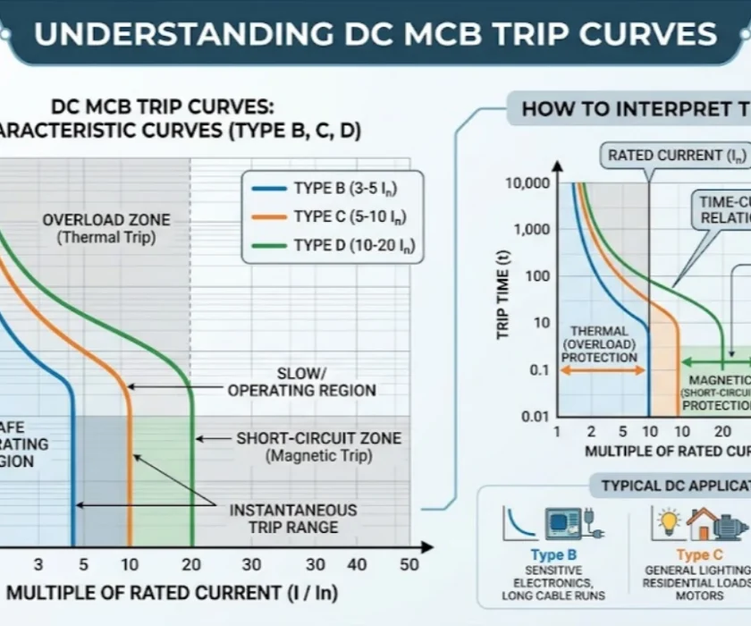
- Trip curve: C-curve for most BESS string applications; the string’s own current profile does not exhibit the high-inrush characteristics that would require D-curve
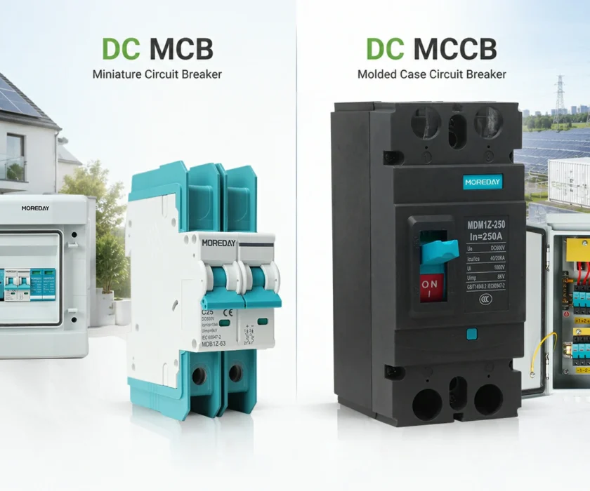
Typical device: DC MCB (for smaller residential and commercial BESS) or DC MCCB (for larger commercial and industrial systems with higher string currents and breaking capacity requirements)
Tier 3 — Bank or Cluster Level
Where multiple strings are combined into a battery bank or cluster before connecting to the inverter or PCS (Power Conversion System), a bank-level DC circuit breaker provides protection for the combined output.
Function: Main isolation point for the battery bank during maintenance, fault response, and commissioning. Provides overcurrent protection for the main DC bus cabling between the battery bank and the PCS. Acts as the primary protection coordination point — it must remain closed while string-level breakers trip on individual string faults.
Device requirements:
- Current rating: total bank continuous current × 1.25, with temperature derating
- Breaking capacity: this is the most critical specification at this tier. The fault current available at the bank output is the full discharge capability of all strings in parallel — potentially 20–100 kA or more for large systems. Standard DC MCBs with 6–10 kA breaking capacity are entirely inappropriate here. A DC MCCB with verified breaking capacity well above the prospective fault current is required. For large utility-scale BESS, supplementary DC fuses in series with the MCCB may be required to achieve the total breaking capacity needed.
- Adjustable trip: strongly recommended. The bank-level device must be coordinated with string-level devices so that string faults clear at Tier 2 without tripping Tier 3. Adjustable magnetic trip thresholds make this coordination straightforward to achieve and verify.
- Non-polarized: mandatory
Tier 4 — System Level (PCS Interface and Grid Disconnect)
The highest tier connects the BESS to the Power Conversion System and ultimately to the AC grid. The DC side of this connection requires a main system disconnect that serves multiple functions: fault protection, maintenance isolation, and rapid shutdown in emergency conditions.
Function: Emergency disconnect capable of interrupting full system fault current. Maintenance isolation point for the entire BESS. May be required to operate under remote command from the EMS (Energy Management System) or fire suppression system.
Device requirements:
- Breaking capacity: must address the full system fault current, which at this point includes contributions from all battery strings and potentially from the grid side through the PCS. This often requires either a high-capacity DC MCCB with electronic trip unit, or a combination of MCCB and high-speed DC fuses.
- Remote trip capability: many BESS installations require the system disconnect to be remotely operable — either by the EMS for normal operational control or by the fire suppression system for emergency response. Specify a shunt trip or under-voltage release coil where remote operation is required.
- Manual lockout: the device must be lockable in the open position for maintenance safety (LOTO — Lockout/Tagout compliance).
- Bidirectional: the PCS draws power from the battery during discharge and pushes power into the battery during charging — the same bidirectional requirement applies at this tier as at all lower tiers.
Battery Chemistry and Its Impact on Protection Selection
Not all battery chemistries behave the same way under fault conditions, and the differences are significant enough to affect DC circuit breaker selection.
LFP (Lithium Iron Phosphate)
LFP is the dominant chemistry in stationary BESS applications due to its cycle life, thermal stability, and safety characteristics. LFP cells are the most thermally stable of the lithium-ion family — they do not enter thermal runaway as readily as NMC under overcharge or short-circuit conditions.
From a protection standpoint, LFP’s key characteristic is its relatively flat discharge curve. Voltage varies little between roughly 20% and 80% state of charge, then drops more sharply at the extremes. This means the DC circuit breaker sees a relatively stable bus voltage during normal operation, simplifying the voltage rating calculation. Use the manufacturer’s specified maximum charge voltage (not nominal voltage) for the rating calculation.
NMC (Nickel Manganese Cobalt)
NMC offers higher energy density than LFP and is used in applications where space and weight matter — some commercial BESS, vehicle-to-grid systems, and certain industrial applications. However, NMC is thermally less stable than LFP under fault conditions. Thermal runaway propagation within an NMC pack is faster and more energetic than in LFP.
This has an important implication for protection: in NMC-based BESS, the speed of fault interruption matters more. A fault that persists for even a fraction of a second longer in an NMC system versus an LFP system carries meaningfully higher thermal runaway risk. For NMC applications, specify DC circuit breakers with faster magnetic trip response — or complement the MCCB with high-speed DC fuses in parallel protection — to minimize fault duration.
VRLA and Flow Batteries
Lead-acid VRLA batteries and flow batteries (vanadium redox and others) have different voltage and current profiles from lithium chemistries. VRLA systems typically operate at lower voltages and can deliver very high short-circuit currents. Flow batteries have more moderate fault current profiles due to their electrolyte flow-dependent power delivery. In both cases, consult the battery manufacturer’s protection specifications directly — the sizing principles described in this guide apply, but the specific parameters differ from lithium systems.
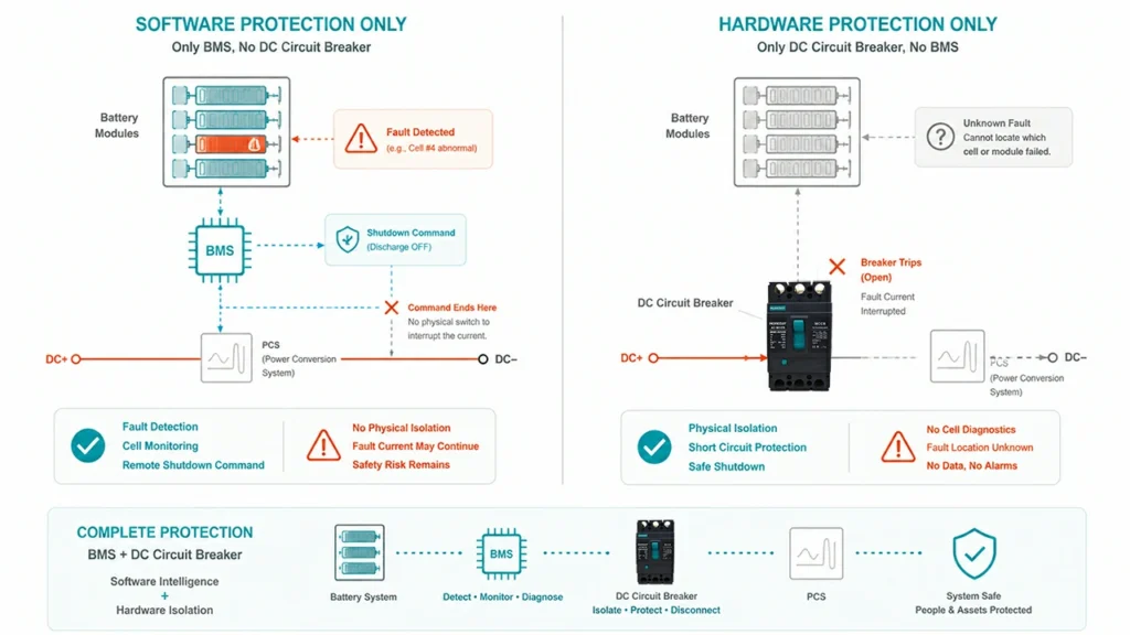
The BMS and DC Circuit Breaker: Complementary, Not Interchangeable
A Battery Management System monitors every cell in the battery bank — voltage, temperature, state of charge, state of health — and responds to out-of-range conditions by commanding the system to reduce power, balance cells, or disconnect. It is the intelligence layer of BESS protection.
A DC circuit breaker is the physical interruption layer. It responds to overcurrent and fault conditions mechanically, without requiring communication from the BMS. It operates even if the BMS has failed.
These two systems are complementary, not redundant. A BMS without an appropriate DC circuit breaker is an unprotected system — the BMS can detect a fault and issue a disconnect command, but if the disconnect mechanism fails or the fault current is too high for the controlled switch to interrupt safely, nothing stops the fault current. A DC circuit breaker without a BMS is blind to cell-level conditions — it cannot detect cell imbalance, gradual capacity fade, or thermal anomalies that precede a fault.
The correct architecture uses both: the BMS handles operational protection and normal disconnect functions through controlled contactors; the DC circuit breaker handles fault interruption at currents and speeds beyond what a contactor can safely manage.
A critical distinction: Contactors — the relay-type switches commanded by the BMS — are not rated to interrupt fault currents. They are designed for normal load switching. Attempting to open a BMS contactor under fault current conditions will cause the contactor contacts to arc and weld shut, defeating the protection entirely. The DC circuit breaker’s role is specifically to interrupt fault currents that would destroy a contactor.
Sizing the DC Circuit Breaker for BESS: Step by Step
Step 1 — Determine maximum continuous current
The maximum continuous current at each protection tier is the basis for the current rating:
- String level: Maximum continuous discharge current of one string. Check the battery manufacturer’s datasheet for the 1C, 0.5C, and maximum continuous discharge rates. Use the maximum continuous rate, not the peak pulse rate.
- Bank level: Sum of all string continuous discharge currents.
- System level: Per the PCS rated power divided by the minimum system voltage (this gives maximum current at the lowest battery state of charge, when voltage is lowest and current is highest for the same power output).
Apply a 1.25× continuous duty factor to the calculated current at each tier to determine the minimum rated current of the DC circuit breaker.
Step 2 — Determine maximum voltage
Use the battery manufacturer’s specified maximum charge voltage — not the nominal voltage. For a multi-string system, this is the voltage of one string (strings in parallel share the same voltage). Apply a 10% margin above the maximum charge voltage to account for overvoltage events and transients:
Minimum voltage rating = Maximum charge voltage × 1.1
Select the next standard DC voltage rating above this value.
Step 3 — Calculate prospective fault current at each tier
At the string level: prospective fault current ≈ (N−1) × string Isc, where N is the number of parallel strings.
At the bank level: prospective fault current ≈ total battery bank short-circuit current. This must be obtained from the battery manufacturer’s specifications or calculated from the bank’s internal resistance. Do not estimate — obtain the actual specification.
At the system level: combine battery fault current with any contribution from the PCS and grid side.
Step 4 — Select breaking capacity
The DC circuit breaker’s breaking capacity (Icu) must exceed the prospective fault current at its installation point with a defined safety margin. IEC 60947-2 requires the actual interrupting rating to be verified under DC conditions — not interpolated from AC ratings.
For string-level protection in small BESS (residential, small commercial): Standard DC MCBs with 6–10 kA breaking capacity are often sufficient if the prospective fault current from parallel strings is within this range.
For bank-level and system-level protection in commercial and industrial BESS: DC MCCBs with 25–100 kA breaking capacity are typically required. For very large systems, supplementary high-speed DC fuses provide an additional breaking capacity layer where the MCCB alone cannot achieve the required interrupting rating.
Step 5 — Confirm non-polarized rating and bidirectional capability
Verify in the manufacturer’s datasheet that the selected DC circuit breaker is explicitly rated for bidirectional current flow and non-polarized operation. This will be stated in the product specification — if it is not explicitly confirmed, assume the device is polarized and select an alternative.
Relevant Standards for BESS DC Protection
Selecting DC circuit breakers for BESS without reference to the applicable standards is incomplete engineering. The key standards governing BESS protection in most markets are:
IEC 62619 — Safety requirements for secondary lithium cells and batteries for use in industrial applications. Addresses BESS safety at the system level, including protection requirements.
IEC 62933-5-2 — Safety requirements for grid-integrated energy storage systems. Specifically addresses grid-scale BESS protection requirements.
NEC Article 706 (US installations) — Energy Storage Systems. Defines disconnecting means, overcurrent protection, and installation requirements for BESS in the US market.
IEC 60947-2 — Low-voltage switchgear and controlgear, circuit-breakers. The device standard that defines how DC circuit breakers must be tested and rated — ensure any device specified for BESS carries DC ratings verified under this standard.
The DC circuit breaker’s product documentation should reference compliance with IEC 60947-2 for DC operation. Devices rated under AC standards only are not appropriate for BESS DC protection, regardless of their current and voltage ratings.
Common Mistakes in BESS DC Circuit Breaker Selection
Using polarized DC breakers in a bidirectional application. This is the single most dangerous selection error in BESS protection. A polarized breaker will fail to extinguish the arc during charging-cycle faults. The result is a sustained arc at full battery fault current — a fire origin.
Sizing breaking capacity on nominal current rather than prospective fault current. A 100A MCCB with 10 kA breaking capacity on a string whose parallel bank can deliver 40 kA fault current is a device that will be destroyed rather than interrupting the fault. Always calculate actual prospective fault current.
Using the nominal battery voltage for voltage rating. Battery voltage at full charge is always higher than nominal. In some chemistries, the difference is significant. Always use maximum charge voltage with a 10% margin, not the nominal label voltage.
Assuming BMS protection is sufficient without a DC circuit breaker. BMS contactors are load-switching devices, not fault interruption devices. Under fault current conditions, a contactor will arc and weld — it will not protect the system.
Neglecting temperature derating in enclosed battery cabinets. BESS enclosures maintain elevated ambient temperatures during charge/discharge cycles. Battery racks in active operation can sustain internal temperatures of 40–55°C continuously. Apply temperature derating to the DC circuit breaker’s current rating based on actual enclosure temperature, not external ambient.
Summary
DC circuit breaker for battery energy storage selection demands attention to three factors that distinguish BESS from other DC applications: bidirectional current flow requiring non-polarized devices, extremely high prospective fault currents requiring verified breaking capacity well beyond the continuous current rating, and a voltage range that spans from minimum discharge to maximum charge voltage rather than a fixed value.
The four-tier protection architecture — cell/module fuses, string-level DC MCBs or MCCBs, bank-level high-capacity MCCBs, and system-level disconnect with remote trip — provides comprehensive, coordinated protection at every point where a fault can develop. Each tier must be sized independently, coordinated with adjacent tiers, and selected from devices with verified DC ratings under IEC 60947-2.
For a full overview of DC protection principles, see our DC Circuit Breaker: All You Need to Know guide. For sizing DC circuit breakers in solar PV systems, see DC Circuit Breaker Solar PV Sizing: 6 Critical Steps. For device type selection, see DC MCB vs DC MCCB: What’s the Difference and How to Choose.
External references: IEC 62619 — Safety requirements for secondary lithium cells and batteries for use in industrial applications (iec.ch); NEC Article 706 — Energy Storage Systems (nfpa.org)