
DistributionSolar

Solar fuse sizing requires matching a fuse’s current rating, DC voltage rating, and protective characteristics to the actual photovoltaic circuit. The correct fuse must carry normal operating current, withstand the maximum system voltage, and provide the required overcurrent protection without exceeding the limits of the PV modules or conductors.
For many conventional PV string installations designed under common U.S. NEC methods, a preliminary fuse current rating is calculated using approximately 1.56 × the module short-circuit current (Isc). However, this multiplier is not universal. The applicable electrical code, equipment ratings, environmental conditions, and fuse manufacturer’s recommendations must also be considered.
This guide covers the essential calculations, explains how to select a gPV fuse, and demonstrates the process using a realistic 1000V solar array example.
1. What Information Is Needed for Solar Fuse Sizing?
Before selecting a fuse, collect the electrical characteristics of the PV modules and the array configuration.
The most important information comes from the module datasheet, system design documents, and applicable installation requirements.
| Parameter | Symbol | Purpose |
|---|---|---|
| Module short-circuit current | Isc | Starting point for current calculations |
| Module open-circuit voltage | Voc | Starting point for maximum DC voltage calculations |
| Voc temperature coefficient | βVoc | Determines voltage increase at lower temperatures |
| Maximum series fuse rating | — | Defines the module manufacturer’s fuse-rating limit |
| Modules connected in series | Ns | Determines string open-circuit voltage |
| Parallel strings | Np | Helps determine possible reverse-current contributions |
| Minimum design temperature | Tmin | Used to calculate maximum PV string voltage |
| Corrected cable ampacity | Iz | Confirms conductor protection compatibility |
| Fuse installation temperature | — | Determines whether temperature derating is necessary |
Understanding Isc, Imp, and Maximum Series Fuse Rating
Three values are particularly important:
- Isc (short-circuit current): The module’s current under short-circuit conditions at specified test conditions.
- Imp (maximum power current): The current at the module’s maximum power point.
- Maximum series fuse rating: The maximum overcurrent protective device rating permitted by the module manufacturer for the specified application.
Isc, rather than Imp, is generally the starting point for conventional PV string overcurrent calculations.
For example, a module with an operating current of 12.2A might have an Isc of 13A. Selecting a 15A fuse merely because it exceeds the operating current would overlook the additional current and installation factors required by the applicable design method.
Similarly, a module marked with a maximum series fuse rating of 25A must not automatically be paired with a 30A fuse simply because the circuit’s calculated current is close to 25A.
The full selection must respect the module manufacturer’s limitations.
2. When Does a Solar PV String Need a Fuse?
Before calculating a fuse rating, determine whether dedicated string overcurrent protection is required.
A solar PV string does not necessarily require a fuse simply because it contains multiple modules.
The decision depends on whether an external current source can supply damaging fault current into the string and whether the connected equipment and wiring can safely withstand that current.
Single PV Strings
A standalone PV string is typically current-limited by the characteristics of its modules.
If there are no additional sources capable of feeding significant current into the string, dedicated string overcurrent protection may not be required, provided the conductors and equipment satisfy the applicable design requirements.
Parallel PV Strings
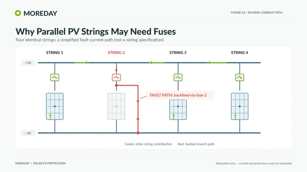
When multiple strings are connected in parallel, a fault in one string may allow current from other strings to flow back into the affected circuit.
For identical strings, a simplified preliminary estimate of the available reverse-current contribution is:
Ireverse ≈ (Np − 1) × Isc
Where:
- Ireverse = estimated reverse-current contribution from other strings
- Np = number of parallel strings
- Isc = module or string short-circuit current at STC
For four identical parallel strings, each with Isc = 13A:
Ireverse ≈ (4 − 1) × 13A = 39A
This illustrates why parallel connections can create a protection requirement even though each individual string is current-limited.
However, the estimate does not account for every operating condition, irradiance effect, inverter contribution, or other connected source. It also does not prove how quickly a particular fuse will operate.
Why the Number of Strings Is Not Enough
A rule such as “three or more strings always require fuses” is too simplistic.
The correct decision must consider the module’s permitted reverse-current or maximum overcurrent protection limits, conductor ampacity, connected sources, and the relevant electrical standard.
For additional guidance, the University of Maryland Extension’s solar wiring and fusing guide explains overcurrent protection requirements and related NEC calculations.
3. How to Calculate the Correct Solar Fuse Amp Rating
The fuse current rating must satisfy two requirements simultaneously:
- It must be sufficient to carry the maximum expected operating current under the applicable conditions.
- It must not exceed the relevant module, conductor, and equipment protection limits.
NEC-Based Solar Fuse Sizing
For conventional photovoltaic source circuits under the commonly used NEC calculation method, maximum circuit current is determined using a factor of 125% of the module short-circuit current:
Imax = 1.25 × Isc
Where:
- Imax = calculated maximum circuit current
- Isc = rated module short-circuit current
For a conventional overcurrent protective device that must be rated at least 125% of this calculated maximum current:
Ifuse,min = 1.25 × Imax
Combining the two calculations:
Ifuse,min = 1.25 × 1.25 × Isc
Therefore:
Ifuse,min = 1.5625 × Isc
This is commonly expressed as approximately 1.56 × Isc.
The calculation assumes the applicable conventional NEC method. Some listed assemblies and equipment arrangements permit different treatment, and project-specific factors can change the result.
The governing NEC edition and the authority having jurisdiction (AHJ) must be checked.
Example: Calculating the Minimum Fuse Current
Assume a solar module has:
- Short-circuit current: 13A
- Maximum series fuse rating: 25A
Calculate the maximum circuit current:
Imax = 1.25 × 13 = 16.25A
Calculate the preliminary minimum fuse rating:
Ifuse,min = 1.25 × 16.25 = 20.3125A
A 20A fuse would be below this calculated minimum.
A 25A gPV fuse becomes a possible candidate, provided that the remaining checks are satisfied.
This does not mean the selected 25A fuse is automatically suitable. Temperature correction, conductor protection, breaking capacity, and fuse operating characteristics remain essential.
IEC-Based Solar Fuse Selection
IEC-based installations must be evaluated under the applicable PV array design requirements and protective device standards.
IEC 62548-1 addresses PV array design, including electrical protection requirements.
IEC 60269-6 specifies supplementary requirements for photovoltaic fuse links.
Unlike a general rule of thumb, the correct IEC selection depends on the circuit being protected, the applicable provisions, and the characteristics of the proposed fuse.
For example, a PV string fuse and a PV sub-array fuse may require different calculations because they carry different currents and protect different parts of the system.
Eaton’s photovoltaic fuse application guide provides practical selection methods for string and array protection, including current factors, fuse limitations, and environmental derating.
The 1.56 factor is useful in the specified NEC-based method and is also used in some manufacturer’s conservative selection recommendations. It should not be presented as a universal requirement for every IEC PV installation.
4. How to Calculate Solar Fuse DC Voltage Rating
Current is only part of solar fuse sizing.
The fuse’s rated DC voltage must be appropriate for the highest voltage it may need to interrupt in the circuit.
This is particularly important for 1000V and 1500V PV systems.
Why Cold Temperature Matters
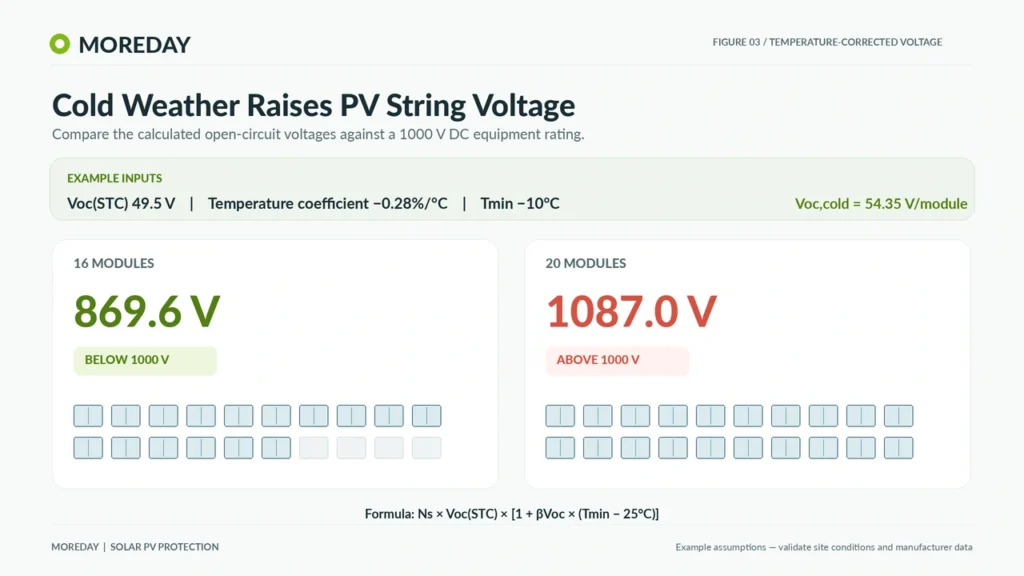
PV module open-circuit voltage generally increases as cell temperature decreases.
Therefore, the maximum string voltage can occur during cold conditions rather than during normal operation.
A simplified temperature-correction relationship is:
Voc,cold = Voc,STC × [1 + βVoc × (Tmin − 25°C)]
Where:
- Voc,cold = temperature-corrected module open-circuit voltage
- Voc,STC = module open-circuit voltage at STC
- βVoc = signed voltage temperature coefficient per °C
- Tmin = minimum design cell temperature used in the calculation
When the manufacturer’s coefficient is provided in %/°C, divide the percentage value by 100 before applying the formula.
The maximum string voltage is then:
Vstring,max = Ns × Voc,cold
The selected fuse must have a suitable DC voltage rating for this calculated condition and any additional applicable design or equipment requirements.
Example: Calculating Maximum PV String Voltage
Assume:
- Module Voc at STC = 49.5V
- Voc temperature coefficient = −0.28%/°C
- Minimum design cell temperature = −10°C
- Modules per string = 16
Convert the temperature coefficient:
βVoc = −0.0028/°C
Calculate the temperature difference:
ΔT = −10 − 25 = −35°C
Calculate the corrected module voltage:
Voc,cold = 49.5 × [1 + (−0.0028 × −35)]
Voc,cold = 49.5 × 1.098 = 54.35V
Calculate the maximum string voltage:
Vstring,max = 16 × 54.351 = 869.62V
On this simplified calculation, a 1000V DC-rated fuse meets the calculated voltage threshold.
For comparison, the same module in a 20-module series string would produce:
Vstring,max = 20 × 54.351 = 1087.02V
A 1000V DC-rated fuse would not meet that voltage requirement.
These calculations are illustrative. Actual designs must verify the correct minimum design temperature, equipment voltage limits, module data, and any additional design margins or factors required by the applicable rules.
The voltage ratings of the inverter, connectors, cables, and other components must also be checked.
5. Worked Example: Selecting a Fuse for a 1000V Solar PV Array
The following example combines current sizing, voltage calculation, and basic coordination checks.
The values represent a hypothetical installation, not the specifications of a particular commercial PV module.
System Configuration
| Parameter | Example Value |
|---|---|
| Module Isc | 13A |
| Module Voc at STC | 49.5V |
| Voc temperature coefficient | −0.28%/°C |
| Maximum module series fuse rating | 25A |
| Modules per string | 16 |
| Parallel strings | 4 |
| Minimum design cell temperature | −10°C |
| Corrected string cable ampacity | 30A, assumed |
| Example fuse ambient derating factor | 0.90, assumed |
| System maximum DC equipment voltage | 1000V |
Calculation 1: Determine Possible Reverse Current
With four parallel strings, the simplified contribution from the three remaining healthy strings is:
Ireverse ≈ (4 − 1) × 13A
Ireverse ≈ 39A
This exceeds the example module’s 25A maximum series fuse rating, indicating that reverse-current protection requires attention.
The actual fault current and required protective response must be assessed for the installation.
Calculation 2: Determine Preliminary Fuse Current Rating
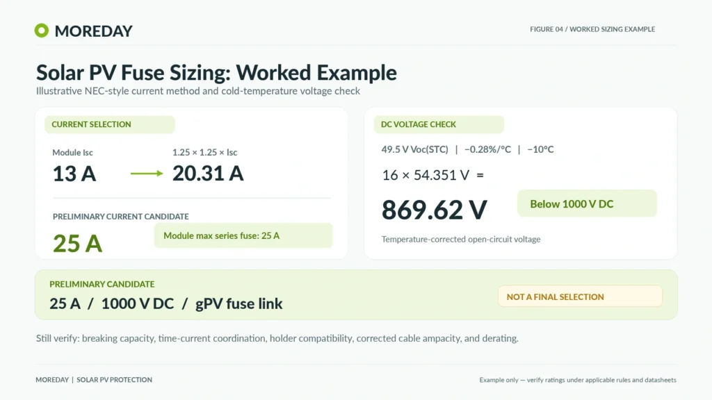
Using the conventional NEC-based example:
Ifuse,min = 1.25 × 1.25 × 13A
Ifuse,min = 20.31A
A 25A fuse is a possible next available rating.
Check it against the module limit:
25A ≤ 25A — Passes the preliminary module-rating check.
Check it against the assumed corrected cable ampacity:
25A ≤ 30A — Passes this simplified conductor-rating check.
The conductor check must still be completed under the applicable installation code, including temperature, grouping, termination, and other adjustment requirements.
Calculation 3: Verify Maximum DC Voltage
From the previous temperature calculation:
Vstring,max = 869.62V
A 1000V DC fuse meets this calculated voltage threshold.
If a manufacturer’s conservative selection method also calls for a 1.20 × STC string Voc voltage check, the result would be:
1.20 × 16 × 49.5 = 950.4V
A 1000V rating also meets this illustrative check.
The appropriate project method must still govern the final selection.
Calculation 4: Apply Fuse Temperature Derating
A fuse installed in a hot combiner box may have a lower effective current-carrying capability than under the manufacturer’s reference conditions.
For this example, assume the actual manufacturer’s derating chart provides a correction factor of 0.90 at the relevant operating temperature.
The effective current-carrying capability of a 25A fuse would be:
25A × 0.90 = 22.5A
This is above the preliminary calculated minimum of 20.31A.
Therefore, the candidate passes this simplified thermal current check.
Important: The 0.90 factor is hypothetical. It must not be applied to a real product unless supported by the selected fuse manufacturer’s documentation.
Calculation 5: Verify the Complete Fuse Assembly
The remaining checks include:
- The selected fuse link is specifically rated for the required DC voltage and gPV application.
- Its breaking capacity is sufficient for the prospective fault current.
- Its time-current characteristics provide appropriate protection against the relevant fault conditions.
- The fuse holder is approved or otherwise specified as compatible with that exact fuse link.
- Terminal ratings, conductor sizes, enclosure heating, and environmental conditions are acceptable.
- The fuse position and conductor arrangement comply with the applicable electrical code.
The estimated 39A reverse current is not proof that every 25A fuse will open within a sufficiently short time. Fuse operation must be evaluated using the actual time-current characteristics and the protected equipment’s withstand limitations.
Preliminary Selection Summary
| Check | Calculated / Assumed Result | Assessment |
|---|---|---|
| Minimum fuse current | 20.31A | 25A candidate |
| Maximum module series fuse | 25A | Candidate does not exceed limit |
| Maximum string voltage | 869.62V | 1000V candidate suitable for this threshold |
| Corrected cable ampacity | 30A | Above 25A candidate |
| Illustrative derated fuse capacity | 22.5A | Above 20.31A |
| Breaking capacity | Not provided | Must verify |
| Fuse operating coordination | Not provided | Must verify |
| Fuse-holder compatibility | Not provided | Must verify |
Preliminary result: A 25A, 1000V DC gPV fuse link is a reasonable candidate for further engineering verification under the stated assumptions.
This is not a final installation approval. The complete selection requires actual manufacturer data, fault-current assessment, fuse characteristics, and applicable code checks.
6. Additional Factors That Affect PV Fuse Selection
Even after calculating the nominal current and voltage ratings, several practical factors can change the final fuse selection.
Fuse Holder Compatibility
A fuse link and its holder must be compatible electrically, thermally, and mechanically.
Confirm the following:
| Item | Required Verification |
|---|---|
| Rated DC voltage | Holder and fuse link must suit the system |
| Fuse dimensions | Actual fuse-link dimensions must match the holder |
| Rated current | Holder and terminals must support the required operating conditions |
| Fuse-link compatibility | Check manufacturer’s supported fuse types and configurations |
| Terminal capacity | Wire size and termination method must be suitable |
| Ambient conditions | Thermal limits and installation derating must be satisfied |
| Short-circuit performance | Verify the rated fuse and holder combination |
MOREDAY supplies several DC fuse holder configurations, including the MDPV-30 1000V DC fuse holder for 10 × 38 mm fuse links and the MDPV-32 1500V DC fuse holder for 10 × 85 mm fuse links.
These products illustrate different installation options. Their exact compatibility with a proposed fuse link must be verified using model-specific technical documentation.
Breaking Capacity and Fuse Characteristics
The rated breaking capacity must be sufficient for the prospective fault current at the applicable DC voltage and other specified test conditions.
A fuse with a suitable nominal current rating may still be unacceptable if its breaking capacity or operating characteristic does not match the circuit.
For PV applications, gPV fuse links are designed for the characteristics of photovoltaic fault currents.
The relevant product requirements are described in IEC 60269-6, while North American PV fuse product requirements are addressed by UL 248-19.
An IEC compliance claim does not establish that a particular product is UL Listed.
Temperature, Irradiance, and Enclosure Conditions
PV installations operate across wide environmental ranges.
Important considerations include:
- Elevated ambient temperature inside a combiner box
- Solar heating of the enclosure
- High irradiance and possible current increases above STC values
- Cable grouping and temperature corrections
- Installation altitude and manufacturer restrictions
- Long-term contact resistance and terminal heating
Using a fuse with a higher ampere rating is not a substitute for solving an enclosure thermal problem.
If the required current rating after derating exceeds the module’s maximum series fuse rating, the design must be revised rather than simply increasing the fuse size.
Common Solar Fuse Sizing Mistakes
Mistake 1: Selecting the fuse using Imp instead of Isc.
The maximum power operating current does not replace the short-circuit current used in conventional PV source-circuit protection calculations.
Mistake 2: Ignoring the maximum series fuse rating.
The selected fuse must not exceed the module manufacturer’s specified limit.
Mistake 3: Using nominal system voltage without cold-temperature correction.
Low temperatures can increase PV string open-circuit voltage above the values calculated from STC data alone.
Mistake 4: Selecting the fuse link without checking the holder.
Matching the physical dimensions is necessary but not sufficient to establish compatibility.
Mistake 5: Applying one sizing multiplier to every installation.
NEC-based methods, IEC-based methods, equipment configurations, and manufacturer requirements may differ.
Mistake 6: Assuming a fuse rated at 25A will immediately open at 26A.
Fuse response depends on time-current characteristics, environmental conditions, and the actual fault current.
7. Solar Fuse Sizing Checklist and MOREDAY Product Selection
A complete PV fuse specification should document the following:
| Selection Item | Required Information |
|---|---|
| PV module data | Isc, Voc, temperature coefficient, maximum series fuse rating |
| Array configuration | Number of series modules and parallel strings |
| Protection requirement | Reverse-current and overcurrent assessment |
| Fuse current | Calculated minimum and applicable maximum limits |
| Fuse voltage | Maximum string voltage under design conditions |
| Fuse type | Appropriate PV protection characteristic |
| Breaking capacity | Available fault current and specified DC ratings |
| Fuse coordination | Time-current behavior and equipment withstand limits |
| Fuse holder | Electrical, mechanical, and thermal compatibility |
| Environmental conditions | Ambient temperature, enclosure, altitude and cable ratings |
| Compliance | Applicable IEC/NEC rules and product documentation |
For PV systems, the correct fuse is not simply the one with the nearest ampere rating. It is the fuse that satisfies the complete electrical protection requirements of the circuit.
MOREDAY DC Fuse Products
MOREDAY provides photovoltaic DC fuse links and fuse holders for solar protection applications, with product families covering 1000V and 1500V DC configurations.
Relevant product resources include:
- MOREDAY DC Fuse and Fuse Holder Product Range
- 1000V / 1500V DC Fuse Links
- MDPV-30 1000V DC Fuse Holder
- MDPV-32 1500V DC Fuse Holder
For EPC projects, PV combiner box assemblies, distributor purchasing, or OEM requirements, provide the following details when requesting selection assistance:
Module model and datasheet → Isc and Voc → Maximum series fuse rating → Series/parallel configuration → System voltage → Installation conditions → Required standards and documentation
This allows the proposed fuse link and holder to be assessed against the actual project requirements.
Conclusion
Solar PV fuse sizing involves more than multiplying the module short-circuit current by a fixed factor. A reliable design considers the need for protection, current rating, cold-temperature voltage, module limitations, cable capacity, fuse operating characteristics, and compatible installation hardware.
Using the calculations in this guide provides a structured starting point, while final equipment selection must be verified against the applicable electrical rules and manufacturer documentation.
Explore MOREDAY’s DC fuse solutions or contact MOREDAY for model-specific specifications and project selection support.