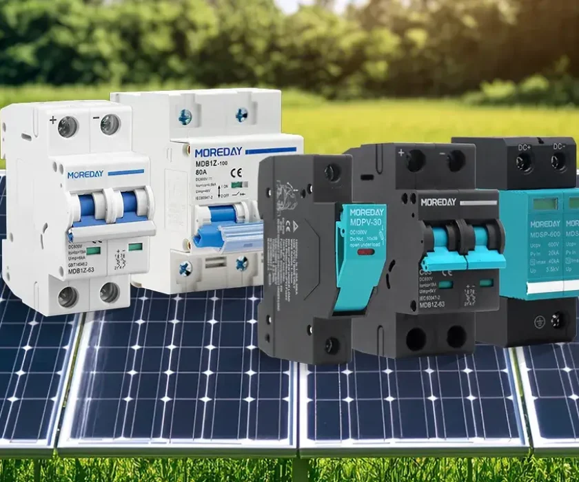
DistributionSolar
AC and DC circuit breakers look nearly identical from the outside — same plastic body, same DIN rail footprint, same ampere ratings on the label. Yet they are fundamentally different devices, and installing the wrong type in the wrong system is one of the most common electrical safety mistakes in solar PV and battery storage installations today.
As solar panels, home battery systems, and EV charging become standard features of modern homes, more people find themselves managing both AC and DC circuits under one roof — often without fully understanding how AC and DC circuit breakers differ, or why that difference matters. This guide explains everything clearly: how each type works, what sets them apart internally, how to identify them, and exactly where each one belongs.
What AC and DC Circuit Breakers Have in Common
Before diving into the differences between AC and DC circuit breakers, it helps to understand why they’re so easily confused — because the similarities are real and significant.
Both AC and DC circuit breakers:
- Monitor current flow continuously and trip automatically when it exceeds a safe level
- Use a thermal element (bimetallic strip) to detect sustained overloads
- Use a magnetic element (electromagnet) to respond instantly to short-circuit currents
- Can be manually reset after a fault is cleared
- Mount on standard 35mm DIN rail and occupy the same physical footprint
- Are rated in amperes using the same scale
These shared characteristics mean that AC and DC circuit breakers are visually indistinguishable at a glance. The critical difference lies not in what triggers them, but in how they stop the current once they have decided to trip. That distinction comes down to one word: the arc.
The Core Difference Between AC and DC Circuit Breakers: Arc Extinction
When any circuit breaker opens its contacts under load, an electrical arc forms across the gap. This arc is a superheated plasma that bridges the space between the contacts, allowing current to keep flowing even after the physical connection is broken. Killing this arc completely — and preventing it from reigniting — is the breaker’s most critical function.
This is where AC and DC circuit breakers diverge entirely.
How AC Circuit Breakers Handle the Arc
Alternating current reverses direction 50 or 60 times per second. Each reversal passes through zero — a brief moment where no current flows at all. These are zero-crossing points, and they occur up to 120 times every second.
AC circuit breakers are engineered around this natural behavior. When the contacts open and an arc forms, the breaker holds its contacts apart and waits — typically no more than 10 milliseconds — for the next zero-crossing. At that instant, the arc loses its energy source and dies on its own. The AC breaker’s arc chamber simply needs to prevent reignition after that point.
The laws of physics work in the AC circuit breaker’s favor. Arc extinction is relatively straightforward, which keeps the internal design compact and cost-effective.
How DC Circuit Breakers Handle the Arc
Direct current flows in one constant direction. There are no zero-crossings. The arc that forms when a DC circuit breaker opens receives an uninterrupted energy supply — and it will not extinguish on its own.
In a DC circuit breaker, the arc:
- Sustains itself as long as the gap voltage is sufficient to maintain ionization
- Grows hotter and more energetic over time — not weaker
- Can reach temperatures exceeding 5,000°C, vaporizing contact material and charring insulation
- In a solar PV system: continues as long as sunlight reaches the panels — potentially for hours
DC circuit breakers must therefore fight the arc using purpose-built internal mechanisms. Nothing extinguishes it automatically. This is the engineering challenge that separates DC circuit breaker design from AC — and why the two types are not interchangeable.
| ⚠ An AC circuit breaker used in a DC system will likely fail to extinguish the arc when it trips. The sustained arc can destroy the breaker internally, weld its contacts together, or ignite surrounding materials — and the breaker may appear to have tripped while the fault continues. |
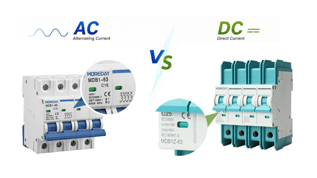
Internal Design: How AC and DC Circuit Breakers Are Built Differently
The difference in arc behavior means AC and DC circuit breakers have very different internal architectures — even when they look identical from the outside.
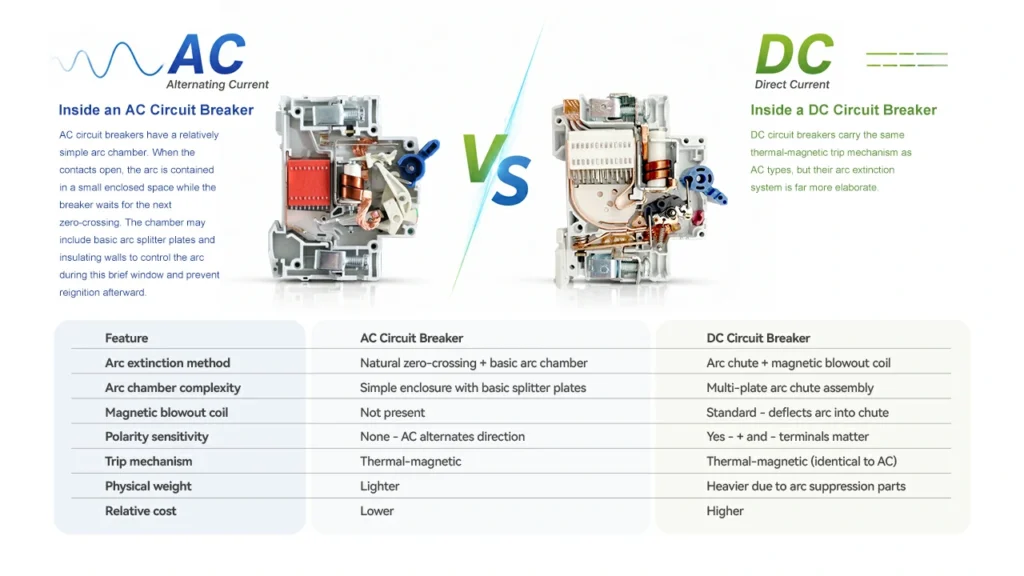
Inside an AC Circuit Breaker
AC circuit breakers have a relatively simple arc chamber. When the contacts open, the arc is contained in a small enclosed space while the breaker waits for the next zero-crossing. The chamber may include basic arc splitter plates and insulating walls to control the arc during this brief window and prevent reignition afterward.
Because the zero-crossing does most of the arc extinction work, the arc suppression system in an AC circuit breaker doesn’t need to be particularly aggressive. This simplicity is why AC circuit breakers are more compact and less expensive than their DC equivalents.
Inside a DC Circuit Breaker
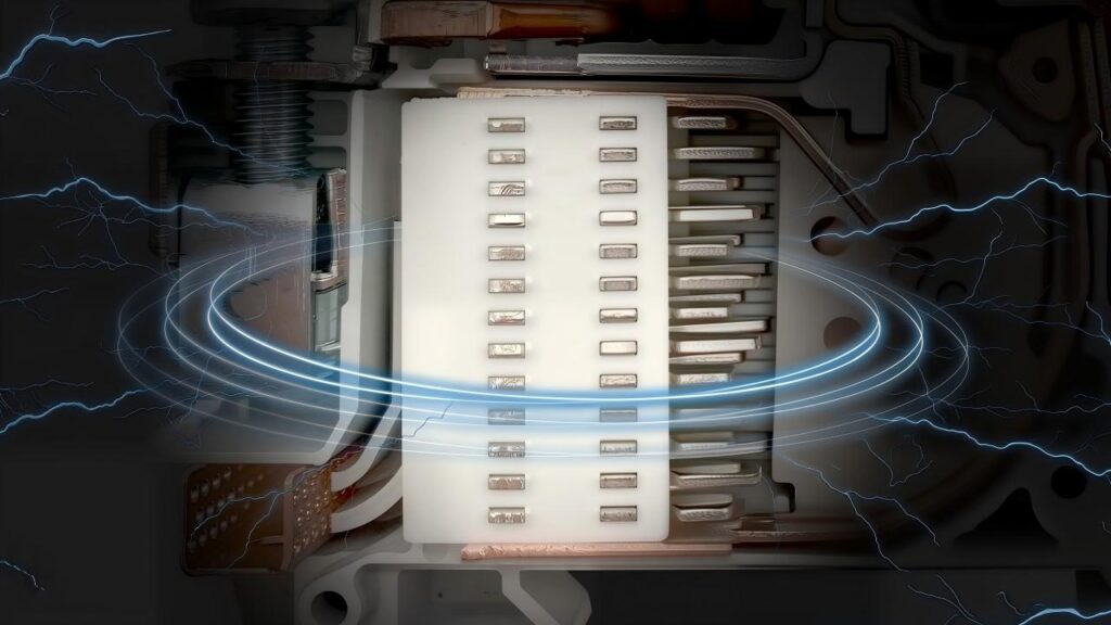
DC circuit breakers carry the same thermal-magnetic trip mechanism as AC types, but their arc extinction system is far more elaborate. Three components work together to kill the arc:
Arc Chute
A stack of parallel metal plates positioned to intercept the arc as it forms. These plates divide the single arc into many shorter series arcs. Each segment adds electrical resistance — collectively building a back-voltage that eventually exceeds the system voltage and starves the arc of energy. The number and configuration of plates determines the maximum DC voltage the breaker can safely interrupt.
Magnetic Blowout Coil
A coil that carries the fault current and generates a proportional magnetic field. This field exerts a physical force on the arc — the Lorentz force — deflecting it rapidly into the arc chute. The larger the fault current, the stronger the field, and the faster the arc is driven into the chute. This self-reinforcing mechanism means the worst faults trigger the fastest response.
Polarity-Optimized Design
The magnetic field direction and arc chute orientation in a DC circuit breaker are calibrated for current flowing one specific way. This is why DC circuit breakers carry polarity markings (+/−) on their terminals and must be wired accordingly. Reversed polarity degrades arc extinction performance without preventing the breaker from carrying current normally — a hidden safety risk.
Together, these components explain why a DC circuit breaker of the same current rating as an AC circuit breaker is physically heavier, internally more complex, and more expensive to manufacture and certify.
| Feature | AC Circuit Breaker | DC Circuit Breaker |
| Arc extinction method | Natural zero-crossing + basic arc chamber | Arc chute + magnetic blowout coil |
| Arc chamber complexity | Simple enclosure with basic splitter plates | Multi-plate arc chute assembly |
| Magnetic blowout coil | Not present | Standard — deflects arc into chute |
| Polarity sensitivity | None — AC alternates direction | Yes — + and − terminals matter |
| Trip mechanism | Thermal-magnetic | Thermal-magnetic (identical to AC) |
| Physical weight | Lighter | Heavier due to arc suppression parts |
| Relative cost | Lower | Higher |
Voltage Ratings: AC and DC Circuit Breakers Are Not Equivalent
One of the most misunderstood aspects of selecting between AC and DC circuit breakers is the voltage rating. A breaker marked “240V” does not mean it can be used on a 240V DC circuit. That figure almost certainly refers to 240V AC, and the two are tested to completely different standards.
Why the Same Voltage Means Different Things
In an AC system, the rated voltage is an RMS (root mean square) value — a mathematical average of the sinusoidal waveform. The actual peak voltage is about 41% higher, but the arc extinction process benefits from the zero-crossing that occurs before and after each peak. The AC circuit breaker never has to fight the arc at full voltage for long.
In a DC system, the voltage is constant. The arc must be extinguished against the full system voltage at all times, with no natural assistance. This is a fundamentally more demanding task — which is why the arc chute and blowout coil in a DC circuit breaker must work so much harder than the arc chamber in an equivalent AC circuit breaker.
Dual-Rated Breakers and the Derating Rule
Some AC and DC circuit breakers are manufactured and tested for both types of service. These dual-rated products show both ratings explicitly on their nameplate — for example, “240V AC / 125V DC.” In these cases, the DC voltage rating is always lower than the AC rating, reflecting the more demanding arc extinction requirements at equivalent DC voltages.
This derating is determined through physical testing and third-party certification. It cannot be applied independently to an AC-only breaker. If the nameplate shows only an AC voltage, that breaker must be treated as unsuitable for DC service — regardless of the numerical similarity.
| 💡 When selecting DC circuit breakers, always look for an explicit DC voltage on the nameplate — such as “1000V DC” or the DC symbol ⎓. Solar PV breakers often carry a “PV” marking as an additional indicator. If only a tilde (~) rating appears, the breaker is AC-only. |
| Voltage Rating Aspect | AC Circuit Breaker | DC Circuit Breaker |
| Label notation | “240V~” or “240V AC” | “1000V DC” or “1000V ⎓” |
| What the value represents | RMS of alternating waveform | Actual continuous voltage |
| Arc energy at rated voltage | Lower — zero-crossing assists | Higher — constant voltage, no natural help |
| Usable in DC at same voltage? | No — not tested for DC arcing | Only within the stated DC rating |
| Dual-rated products | Yes — DC rating will be stated | DC rating always lower than AC equivalent |
How to Tell AC and DC Circuit Breakers Apart
Because AC and DC circuit breakers share the same physical form factor, label reading is the only reliable method of identification without opening the device. Here is what to look for:
Check the Voltage Marking First
- AC circuit breaker: Voltage followed by a tilde (~) or the letters “AC” — e.g., “230V~”, “240V AC”. This breaker is not DC-rated.
- DC circuit breaker: Explicit DC voltage with the ⎓ symbol or the letters “DC” — e.g., “1000V DC”, “1500V ⎓”. May also appear as a dual-rating: “400V AC / 220V DC”.
- “PV” label: Many DC MCBs designed for solar string protection carry a PV marking — a quick visual shortcut for solar installers.
Look for Polarity Markings
DC circuit breakers typically show “+” and “−” terminal markings. AC circuit breakers carry no such markings — polarity is irrelevant in alternating current systems.
Verify the Certification
Both AC and DC circuit breakers should reference IEC 60947-2 or UL 489. However, IEC 60947-2 certification for AC does not imply DC suitability. The certification must specifically include a DC voltage rating. CE marking alone is not sufficient evidence that a breaker is DC-rated.
| Identifier | AC Circuit Breaker | DC Circuit Breaker |
| Voltage symbol | ~ (tilde) or VAC | ⎓ or VDC |
| Typical voltage values | 120V, 230V, 240V, 415V | 250V DC, 600V DC, 1000V DC, 1500V DC |
| Polarity markings | None | Often + and − on terminals |
| “PV” marking | Never | Common on solar-rated MCBs |
| Weight (same amp rating) | Lighter | Noticeably heavier |
Where AC and DC Circuit Breakers Belong in a Modern Home
A home with solar panels and battery storage operates both AC and DC circuits simultaneously. Each section of the system requires the correct type of breaker — and understanding the layout helps clarify exactly where AC circuit breakers end and DC circuit breakers begin.
AC Circuit Breakers: The Grid-Connected Side
AC circuit breakers protect every circuit connected to the utility grid — the alternating current that powers lights, sockets, appliances, and most household loads. In a typical residential installation, AC circuit breakers are found in:
- The main distribution board — protecting individual lighting and socket ring circuits
- The AC output of a solar inverter — the inverter converts DC from the panels into AC for home use; this output is protected by a standard AC circuit breaker
- EV Level 2 charger circuits — these operate on AC and use AC circuit breakers, typically paired with an RCD or RCBO
- Air conditioning, heat pump, and large appliance circuits
DC Circuit Breakers: The Solar and Battery Side
DC circuit breakers protect the direct current portions of the system — from the solar panels through to the inverter input, and across battery connections. The voltages here are often significantly higher than household AC levels. DC circuit breakers are needed at:
- String protection: One DC circuit breaker per string of solar panels, protecting against faults within a single string without shutting down the whole array
- Main DC disconnect: A DC circuit breaker between the array output and the inverter input — required by most electrical codes as a safe isolation point
- Battery connections: DC circuit breakers between the battery bank and the inverter-charger, sized for bidirectional current flow
- DC combiner boxes: Where multiple strings are aggregated, each string is typically protected by a DC fuse or DC MCB before the common output
| 💡 In a typical string-inverter solar system, the DC voltage between the panels and the inverter ranges from 300V to 600V DC. This is why the DC circuit breakers used here must carry a voltage rating that matches the actual system voltage — an AC circuit breaker with a similar-looking 240V or 400V label is not rated for DC service at those levels. |
| System Location | Current Type | Correct Breaker | Typical Rating |
| Individual solar panel strings | DC | DC MCB (string protection) | 10–16A, 600–1000V DC |
| Array combiner to inverter | DC | DC MCB or MCCB (main disconnect) | 25–63A, 1000–1500V DC |
| Battery bank terminals | DC | DC MCB or MCCB (bidirectional) | Sized to battery max current |
| Inverter AC output | AC | Standard AC MCB | 20–40A, 230V AC |
| Main distribution board | AC | AC MCBs / RCBOs | Various, 230–240V AC |
| EV Level 2 charger circuit | AC | AC MCB + RCD | 32A, 230V AC |
Can AC and DC Circuit Breakers Be Used Interchangeably?
This is the most frequently asked question when people first learn that AC and DC circuit breakers are different products — and the answer requires some nuance.
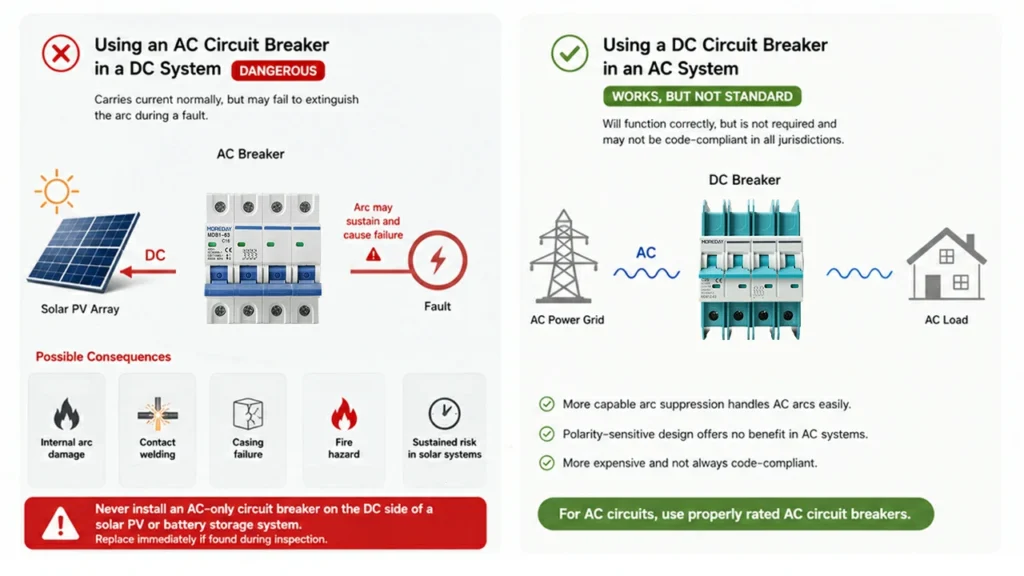
Using an AC Circuit Breaker in a DC System
This is the dangerous substitution. Under normal operating conditions, an AC circuit breaker placed in a DC circuit carries the current without obvious problems. The risk appears only when a fault occurs and the breaker attempts to trip.
Because the AC circuit breaker has no arc chute or magnetic blowout coil adequate for DC, the arc that forms when the contacts open may sustain itself rather than extinguishing. Possible consequences include:
- Internal arc damage — the arc burns through insulation and degrades internal components
- Contact welding — the sustained arc fuses the contacts together so the breaker cannot actually isolate the circuit despite appearing tripped
- Casing failure — extreme arc energy can cause the breaker body to crack or fail
- Fire — carbonized insulation and sustained heat generation create an ignition risk
In solar PV systems, this risk is compounded: the panels continue supplying current throughout daylight hours regardless of the fault, meaning an AC circuit breaker that fails to extinguish a DC arc may sustain that arc for hours.
| ⚠ Never install an AC-only circuit breaker on the DC side of a solar PV or battery storage system. If AC circuit breakers are discovered on DC circuits during an inspection, they should be replaced before the system is re-energized. |
Using a DC Circuit Breaker in an AC System
A DC circuit breaker placed in an AC circuit will function — its more capable arc suppression system handles AC arcs without difficulty. However, using DC circuit breakers in AC applications is not standard practice and may not be code-compliant in all jurisdictions. DC circuit breakers are more expensive, and their polarity-sensitive design offers no benefit in an AC system. For AC circuits, use properly rated AC circuit breakers.
Dual-Rated Breakers: The Legitimate Exception
Some circuit breakers are manufactured and tested for both AC and DC service, with both ratings stated on the nameplate. These dual-rated products are a legitimate solution where AC and DC requirements overlap. The DC voltage rating on a dual-rated breaker is always lower than the AC rating — a manufacturer-tested and certification-verified figure that cannot be assumed or independently calculated for single-rated products.
| ✔ The only safe approach for DC circuits: select a circuit breaker with an explicit DC voltage rating that meets or exceeds the maximum system voltage. When in doubt, choose a purpose-built DC-rated breaker from a certified manufacturer. |
AC and DC Circuit Breakers: Complete Comparison
| Characteristic | AC Circuit Breaker | DC Circuit Breaker |
| Current type | Alternating — reverses direction at 50/60 Hz | Direct — constant direction |
| Zero-crossing present | Yes — up to 120 per second | No — current is continuous |
| Arc extinction mechanism | Zero-crossing + basic arc chamber | Arc chute + magnetic blowout coil |
| Arc extinction difficulty | Relatively straightforward | Significantly harder — active suppression required |
| Polarity sensitivity | None | Yes — +/− terminals must be correctly wired |
| Voltage rating notation | 230V~, 240V AC, 415V AC | 250V DC, 600V DC, 1000V DC, 1500V DC |
| Interchangeable? | Not safe in DC — arc will not extinguish | Works in AC but not recommended or code-compliant |
| Dual-rated versions exist? | Yes — with explicit DC voltage on nameplate | Yes — with explicit AC voltage on nameplate |
| Physical size | Compact, lighter | Same DIN footprint, heavier internals |
| Relative cost | Lower | Higher |
| Trip mechanism | Thermal-magnetic | Thermal-magnetic (identical principle) |
| Typical residential use | Distribution board, AC loads, inverter output | Solar strings, battery bank, DC disconnect |
| Key standard (IEC) | IEC 60947-2 (AC rated) | IEC 60947-2 (with DC voltage rating) |
| Key standard (US/Canada) | UL 489 | UL 489 (with explicit DC marking) |
Common Mistakes When Working with AC and DC Circuit Breakers
Installing an AC circuit breaker on the DC side of a solar system
The most frequent and most dangerous error. The DC portion of a PV installation — from the panels through the combiner box to the inverter input — must use DC circuit breakers throughout. An AC circuit breaker here may pass current normally but will fail unsafely under fault conditions.
Assuming a 600V AC rating equals a 600V DC rating
These are separate certifications with different arc energy requirements. A 600V AC circuit breaker is not suitable for 600V DC service unless it explicitly states “600V DC” on the nameplate. If you see only a tilde (~) symbol, it is AC-only.
Wiring a DC circuit breaker with reversed polarity
Connecting the positive and negative conductors to the wrong terminals on a DC circuit breaker won’t prevent it from carrying current — but it will compromise arc extinction performance when a fault occurs. Always follow the wiring diagram shown on the breaker body.
Using a 1-pole breaker where a 2-pole is required
In ungrounded or floating DC systems — which includes most residential solar and battery installations — both conductors should be interrupted simultaneously. A 1-pole DC circuit breaker disconnects only one conductor. Use 2-pole DC circuit breakers for full isolation.
Purchasing uncertified DC circuit breakers on price alone
The market for DC circuit breakers includes products with questionable or fabricated ratings. A low-cost breaker claiming “1000V DC” without verifiable IEC 60947-2 or UL 489 certification may not safely interrupt fault current at that voltage. Always verify third-party certification before purchase.
Frequently Asked Questions
Conclusion
The difference between AC and DC circuit breakers comes down to a single physical reality: DC arcs do not extinguish themselves. Without zero-crossings to interrupt the flow of energy, a DC arc will sustain itself indefinitely unless forcibly killed by the breaker’s internal arc suppression system. AC circuit breakers are not built to do this — and using them in DC circuits creates a fault mode that is invisible from the outside while remaining actively dangerous inside.
For anyone managing a modern home energy system — solar panels, battery storage, or EV charging infrastructure — the practical rules are clear: use AC circuit breakers on the AC side, use DC circuit breakers on the DC side, verify voltage ratings carefully, and always buy from manufacturers with verifiable certifications. AC and DC circuit breakers each do their job reliably when installed in the right place. The problems arise only when they are not.