
DistributionSolar
Choosing a surge protection device (SPD) for a solar photovoltaic (PV) system requires more than matching a voltage rating or selecting the highest discharge-current value. The correct choice depends on the maximum PV system voltage, the installation location, lightning exposure, grounding arrangement, required protection level, and applicable electrical standards.
A solar PV installation may require surge protection on the DC side, the AC side, or both, depending on its design and risk assessment. The selected SPD must be suitable for the circuit it protects and coordinated with the other protective measures in the system.
This guide explains how to assess SPD type, voltage ratings, discharge-current parameters, protection level, and installation requirements when specifying surge protection for solar PV projects.
Why Do Solar PV Systems Need Surge Protection?
Solar PV systems contain electrical and electronic equipment that can be affected by transient overvoltages. These disturbances may result from nearby or direct lightning events, switching operations, or surges conducted through connected power and signal circuits.
Potentially affected equipment includes:
- PV inverters and their electronic components
- DC combiner boxes and associated protection devices
- AC distribution equipment
- Monitoring and communication equipment
- Other connected control and power electronics
An SPD helps limit transient overvoltage by providing a path for surge current and limiting the voltage that appears across the protected circuit. Its effectiveness depends on correct selection, installation, grounding, and coordination with the system.
An SPD does not prevent lightning strikes, eliminate every surge, or replace the need for proper bonding, grounding, external lightning protection where required, and equipment designed for the installation environment.
Identify Where Surge Protection Is Required
Before choosing an SPD, identify the parts of the PV installation that need protection. A typical system may have DC circuits between the PV array and inverter, AC circuits between the inverter and the distribution network, and separate communication or monitoring circuits.
DC-Side Surge Protection
DC SPDs are designed for the specific characteristics and voltage ratings of DC circuits. In solar PV systems, they may be installed at locations such as a PV combiner box or inverter DC input, depending on the electrical design and applicable requirements.
The selection should account for the maximum PV voltage, the SPD’s DC ratings, the required protection level, lightning exposure, cable routing, grounding, and the inverter manufacturer’s instructions.
A DC SPD must be specifically suitable for the intended PV circuit. An AC SPD should not be substituted simply because its nominal voltage appears similar.
For projects that use a combiner box, review the overall arrangement and the protective devices specified for that assembly. See the MOREDAY guide to DC combiner boxes.
AC-Side Surge Protection
The AC side of a PV installation may also require surge protection. The appropriate SPD depends on the AC system configuration, voltage, earthing arrangement, installation location, lightning risk, and local requirements.
AC and DC SPDs are designed for different electrical conditions. Their ratings and intended applications must be checked separately.
Communication and Monitoring Circuits
If a PV installation uses external monitoring, communication, or control wiring, assess whether these circuits also require suitable surge protection. The correct device depends on the signal type, operating voltage, connection method, and equipment requirements.
Protecting only the power circuits may not address every surge path in a complex installation.
Understand SPD Types and Their Applications
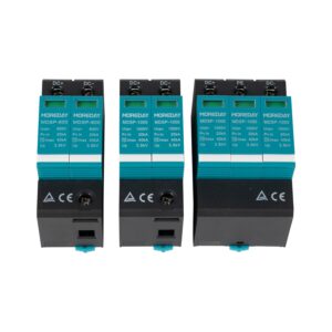
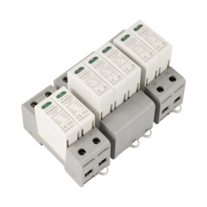
SPD types indicate defined performance classifications under the relevant standards. They should not be treated as universal labels for a single installation location or as interchangeable products.
For low-voltage AC installations, Type 1, Type 2, and Type 3 SPDs are commonly discussed under the applicable standards. PV DC SPDs have their own product-standard and application requirements. Always verify the classification and intended circuit of the exact device.
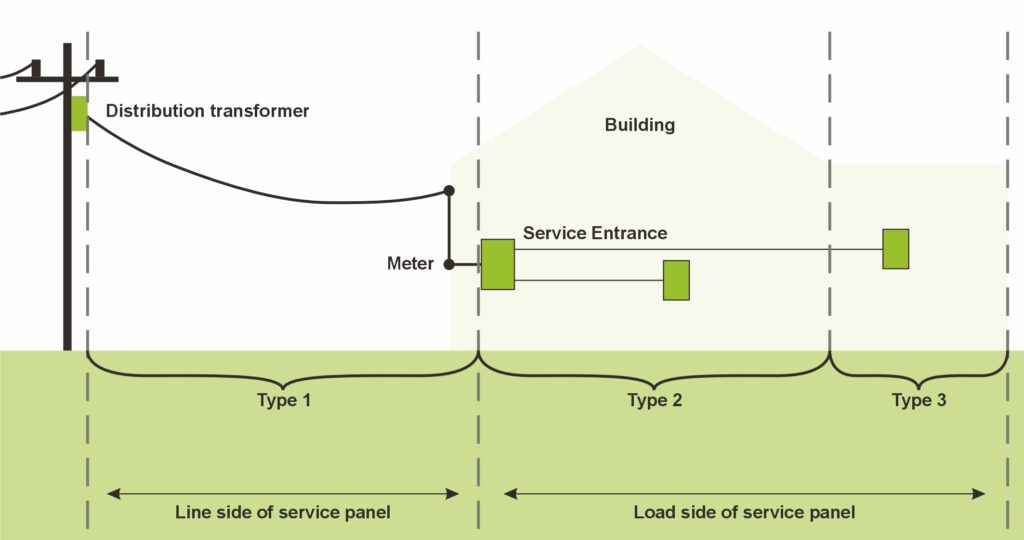
Type 1 SPD
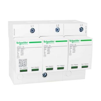
A Type 1 SPD is designed to handle specified partial lightning-current conditions and is selected where the installation risk assessment and applicable requirements call for this level of protection.
Type 1 devices are often associated with installations exposed to lightning-current effects, including certain systems with external lightning protection. Their suitability and installation position must be determined from the protection concept and relevant standards.
Do not assume that every solar PV project requires a Type 1 SPD solely because it is installed outdoors.
Type 2 SPD
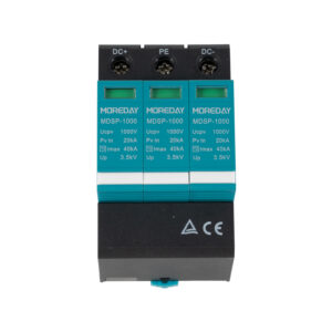
A Type 2 SPD is designed to protect against specified transient overvoltages, including those caused by switching and residual lightning effects, within its rated application.
Type 2 devices are widely used in electrical distribution systems. Suitable PV DC versions may be selected for solar DC circuits when their ratings and classification meet the project requirements.
The device must be suitable for the actual circuit voltage and protection arrangement.
Type 3 SPD
A Type 3 SPD provides additional protection close to sensitive equipment in applications where this level of protection is appropriate. It is generally used as part of a coordinated protection arrangement rather than as a universal replacement for upstream protection.
Whether Type 3 protection is appropriate for a particular PV-related circuit depends on the equipment, circuit type, applicable standards, and the complete protection design.
Combined Type 1+2 SPD
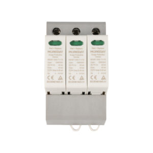
A combined Type 1+2 SPD incorporates the functions associated with both classifications under its applicable product standard. It may simplify equipment arrangements in suitable applications.
However, a combined device is not automatically suitable for every location or every PV system. Confirm its intended circuit, tested classification, voltage ratings, protection characteristics, and installation requirements.
The key principle is to choose the SPD classification based on the system’s risk and protection design—not simply on the product name or a generic installation rule.
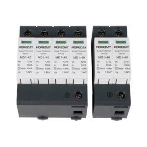
Check the Maximum PV System Voltage
Voltage compatibility is one of the most important selection requirements for a DC SPD.
Account for Maximum Open-Circuit Voltage
A PV string’s open-circuit voltage changes with temperature. Under low-temperature conditions, the string voltage may rise above its value at standard test conditions.
When selecting a DC SPD, the designer should determine the maximum expected PV voltage using the module specifications, the number of modules connected in series, the lowest expected cell temperature, and the calculation method required by the applicable design rules.
Do not select an SPD solely from the nominal system-voltage label.
Understand Maximum Continuous Operating Voltage (Uc)
The maximum continuous operating voltage, commonly designated (U_c), is the maximum voltage that may be continuously applied to the SPD under the conditions specified by its manufacturer.
For a PV DC SPD, (U_c) must be suitable for the actual circuit and its maximum expected voltage. Choosing an unsuitable value can compromise protection or cause the device to operate outside its intended conditions.
The required rating must be checked against the system design and the manufacturer’s technical documentation.
Do Not Confuse Different Voltage Ratings
Product pages may show several voltage-related values. These should not be treated as equivalent.
| Parameter | Meaning | What to check |
|---|---|---|
| Nominal system voltage | The system’s stated voltage class | Confirm that it describes the intended application |
| (U_c) | Maximum continuous operating voltage | Confirm compatibility with the maximum expected circuit voltage |
| (U_p) | Voltage protection level | Check whether the protection level is suitable for the equipment and insulation coordination |
| Rated voltage or other declared voltage values | A value defined by the relevant product documentation | Confirm the exact definition in the manufacturer’s datasheet |
Use the definitions and test conditions specified for the actual product. Do not compare voltage values from different products without confirming that they represent the same parameter.
Evaluate the SPD’s Discharge-Current Ratings
Discharge-current ratings indicate how the SPD is tested and what surge-current conditions it is designed to handle. They must be interpreted alongside the SPD type, waveform, voltage rating, and intended application.
Nominal Discharge Current (In)
(I_n) is the nominal discharge-current parameter used for the applicable SPD classification and test conditions. It is commonly specified for Type 2 SPDs.
When comparing devices, verify the stated waveform and test standard. The same numerical value may not mean the same thing when the test conditions differ.
Maximum Discharge Current (Imax)
(I_{\max}) is the maximum discharge-current parameter declared for the relevant test conditions, commonly associated with Type 2 SPD specifications.
A higher (I_{\max}) value does not automatically mean a device provides a lower protection level or is the best choice for every installation. Compare it with the SPD’s other ratings and the project’s protection requirements.
Impulse Discharge Current (Iimp)
(I_{\mathrm{imp}}) is associated with the specified impulse-current test for Type 1 SPDs under the relevant standards.
It should not be directly compared with an (I_n) or (I_{\max}) value unless the test conditions and definitions are equivalent.
Compare Like with Like
When reviewing SPD datasheets, confirm:
- The SPD type and applicable product standard
- The declared current parameter and its test waveform
- The maximum continuous operating voltage
- The voltage protection level
- The intended DC or AC circuit
- Any additional installation or coordination requirements
Avoid choosing an SPD solely because its headline kA rating is higher than another product’s rating.
Check the Voltage Protection Level (Up)
The voltage protection level, (U_p), is an important factor when evaluating how well an SPD limits transient voltage under the specified test conditions.
The selected SPD should provide a protection level appropriate for the withstand capability of the connected equipment and the installation’s insulation coordination requirements.
However, comparing (U_p) alone is not enough. Actual protection also depends on factors such as the SPD’s location, conductor routing, connection length, grounding and bonding arrangements, and the characteristics of the incoming surge.
Keep the SPD connections as short and direct as required by the installation instructions and applicable standards. Poor routing can reduce the effectiveness of the protection arrangement.
Assess Lightning Risk, Grounding, and Protection Coordination
The correct SPD arrangement depends on the overall electrical installation, not just the device’s technical specifications.
Before selecting the final configuration, review:
- The site’s lightning exposure and the project risk assessment
- Whether an external lightning protection system is installed or required
- Grounding and equipotential bonding arrangements
- The distance between the PV array, inverter, and relevant distribution equipment
- Cable routing and the possible paths through which surges may enter
- The manufacturer’s instructions for the inverter and connected equipment
- The requirements of the applicable electrical codes and standards
Depending on the system design, more than one SPD may be needed at different locations. The devices should be coordinated as part of a complete protection concept.
Do not assume that installing a single SPD at one location protects every circuit and every item of equipment in a PV installation.
Verify the Applicable Standards and Product Documentation
The correct standard depends on the circuit, SPD category, market, and product. Different requirements may apply to PV DC SPDs, low-voltage AC SPDs, and communication-line protection devices.
Before purchasing or specifying an SPD, verify:
- The exact product classification and intended application
- The applicable product standard and edition
- The declared voltage and discharge-current ratings
- The manufacturer’s installation instructions
- Any certification or conformity documentation required for the target market
- Compatibility with the inverter, combiner box, and other connected equipment
Do not assume that a general reference to IEC, EN, UL, or another standards family means that every model complies with every related standard. Confirm the exact standard and evidence for the selected product and configuration.
Solar PV SPD Selection Checklist
Use the following checklist when reviewing an SPD for a solar PV project.
| Selection item | Question to confirm |
|---|---|
| Circuit type | Is the device intended for the DC PV circuit, AC circuit, or a communication line? |
| SPD classification | Does the classification match the required protection concept and applicable standard? |
| Maximum voltage | Is the device’s (U_c) suitable for the maximum expected circuit voltage? |
| Protection level | Is (U_p) appropriate for the connected equipment and insulation coordination? |
| Discharge-current ratings | Are (I_n), (I_max), or (I_imp) appropriate for the selected SPD type and test conditions? |
| Lightning and grounding | Have lightning risk, external protection, grounding, and bonding been assessed? |
| Installation | Are the location, wiring route, conductor length, and mounting method appropriate? |
| Compatibility | Is the SPD compatible with the inverter and other protective equipment? |
| Documentation | Are the datasheet, installation instructions, and required compliance documents available? |
If any of these items remains unconfirmed, do not finalize the selection based on a headline voltage or current rating alone.
Conclusion
Selecting the right SPD for a solar PV system requires a coordinated assessment of circuit type, maximum system voltage, SPD classification, discharge-current ratings, voltage protection level, lightning risk, grounding, and applicable standards.
The correct device is not necessarily the one with the highest kA rating or the lowest published (U_p). It is the device whose verified specifications and installation requirements match the actual PV system and its protection design.
For project-specific selection, explore the MOREDAY SPD product range and confirm the required circuit type, voltage rating, SPD classification, and technical specifications against the project’s electrical drawings and the manufacturer’s documentation.