
DistributionSolar
A gPV fuse is a photovoltaic fuse link designed to provide full-range DC overcurrent protection within its specified breaking range for solar PV strings and arrays. The designation gPV identifies a protection characteristic defined in IEC 60269-6, which addresses the special electrical conditions found in photovoltaic systems.
Unlike conventional electrical supplies, solar panels have limited short-circuit current capabilities. This makes PV fault protection challenging, particularly when reverse current flows from healthy parallel strings into a faulted string.
gPV fuses are engineered to address these conditions while interrupting direct current at the specified voltage and fault-current levels.
This guide explains what gPV means, how photovoltaic fuse links differ from general-purpose fuses, which requirements IEC 60269-6 establishes, and what engineers should verify before selecting PV protection components.
What Does gPV Mean on a Fuse?
The designation gPV combines two elements of the IEC fuse classification system:
- g: A full-range breaking-capacity fuse link, capable of interrupting currents within its specified breaking range.
- PV: A utilization category intended for photovoltaic energy systems.
Therefore, gPV identifies a fuse characteristic developed specifically for photovoltaic protection.
The designation is not a manufacturer’s brand, a voltage rating, or a certification mark.
It describes the fuse’s intended application and operating characteristics.
What Does Full-Range Breaking Capacity Mean?
In the IEC classification system, full-range fuse links are designated by the letter “g”.
This differentiates them from partial-range fuse links, designated by the letter “a”.
A full-range fuse link is intended to interrupt specified overcurrents across its defined breaking range, including relevant overload and short-circuit conditions.
However, full-range protection does not mean that a fuse immediately interrupts every current above its rated amperage.
Its operating behavior still depends on current magnitude, duration, applicable conventional operating requirements, and manufacturer-specific time-current characteristics.
Similarly, the term does not imply protection against every possible PV fault, especially faults that do not produce sufficient overcurrent.
How to Identify a gPV Fuse
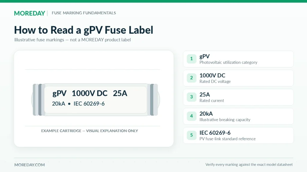
A photovoltaic fuse link may carry markings such as:
| Marking | Meaning |
|---|---|
| gPV | Photovoltaic utilization category |
| 1000V DC | Rated direct-current voltage |
| 25A | Rated current |
| 20kA | Rated breaking capacity, where specified |
| IEC 60269-6 | Referenced PV fuse-link standard |
| Manufacturer/model | Identifies the specific product and technical documentation |
These markings must be interpreted together.
For example, gPV 25A 1000V DC describes a PV fuse link with a 25A rated current and 1000V DC rated voltage.
It does not establish that the fuse is suitable for every 1000V photovoltaic installation.
The complete circuit and product characteristics must still be checked.
For a broader introduction to direct-current protection, see What Is a DC Fuse? How It Works, Types, Ratings & Solar PV Uses.
Why Do Solar PV Systems Need gPV Fuse Characteristics?
Photovoltaic power sources have different electrical characteristics from conventional grid-powered circuits.
In many conventional distribution networks, a short circuit can produce a current many times greater than the normal operating current.
Photovoltaic modules, however, are inherently current-limited.
Under typical test conditions, the short-circuit current of a PV module is only moderately higher than its maximum power operating current.
Consequently, certain PV faults can produce relatively low overcurrents.
Low Fault Currents in PV Arrays
Consider a simplified example using identical PV strings.
Each string has:
- Short-circuit current (Isc): 13A
- Maximum series fuse rating: 25A
If four strings are connected in parallel and one string develops a fault, the other three strings may contribute current to the faulted branch.
A preliminary estimate at STC is:
Ireverse ≈ (4 − 1) × 13A = 39A
The actual current will depend on irradiance, circuit conditions, and additional connected sources.
Although 39A may appear relatively small compared with the fault current available from a conventional electrical supply, it can exceed the affected PV modules’ permitted overcurrent limits.
A correctly specified PV fuse must therefore provide suitable protection under the particular fault-current conditions.
Why Ordinary Fuse Characteristics May Be Unsuitable
A general-purpose fuse may have adequate current and voltage ratings but different operating characteristics.
For example, its time-current behavior may not provide the required protection against the comparatively low overcurrents associated with certain PV faults.
The appropriate fuse must be capable of interrupting the relevant current at the system voltage, and its operating behavior must coordinate with the limits of the protected components.
This is why the gPV utilization category is important.
How Does a gPV Fuse Interrupt DC Current?
The basic operating process is:
Fault current → Fuse element heating → Element melting → DC arc formation → Arc extinction → Circuit interruption
The design of the fuse element and the arc-extinguishing arrangement determines its response to fault current.
Direct current does not pass naturally through zero at regular intervals as alternating current does.
The fuse must therefore extinguish the DC arc within its specified voltage and fault-current limits.
Many high-breaking-capacity cylindrical PV fuses incorporate ceramic bodies and arc-quenching filler materials.
However, the precise construction and performance depend on the product design.
A gPV fuse is a replaceable protective component, not a resettable circuit breaker or general-purpose load-break switch.
What Does IEC 60269-6 Require for gPV Fuses?
IEC 60269-6:2010+A1:2021 is the international standard covering supplementary requirements for fuse links used to protect solar photovoltaic energy systems.
Its requirements complement the general fuse requirements of IEC 60269-1.
The standard addresses PV fuse links used in equipment for protecting photovoltaic strings and arrays, primarily in circuits with nominal voltages up to 1500V DC.
Main Technical Requirements
IEC 60269-6 includes requirements associated with:
- Rated DC voltage.
- Rated current.
- Breaking range and breaking capacity.
- Conventional fusing and non-fusing characteristics.
- Time-current operating behavior.
- Temperature-rise and power-dissipation characteristics.
- Performance under specified electrical fault conditions.
These requirements help establish whether a fuse link can provide the intended performance in photovoltaic applications.
They should not be confused with the system design requirements determining where a fuse is necessary.
Breaking Capacity and Low-Overcurrent Performance
Two different characteristics are important.
Rated breaking capacity describes the maximum prospective fault current the device is rated to interrupt under specified test conditions.
Low-overcurrent performance describes the behavior of the fuse at currents relatively close to its rated current.
IEC 60269-6 establishes a minimum rated DC breaking capacity of 10kA for the applicable PV fuse links.
Individual products may be rated for higher breaking capacities, such as 20kA or 30kA, depending on their tested design.
However, a high breaking-capacity value does not independently establish suitable operation at every lower overcurrent level.
The relevant conventional-current requirements and time-current characteristics must also be assessed.
What Does 1.35 × In Mean?
Some photovoltaic fuse datasheets refer to 1.35 × In, where In is the fuse’s rated current.
For example, for a 20A fuse:
1.35 × 20A = 27A
This figure appears in certain PV fuse operating and interruption specifications, but its exact meaning depends on the particular test condition, fuse type, and manufacturer’s documentation.
It must not be interpreted as a universal instantaneous operating threshold.
A fuse rated at 20A does not necessarily open immediately at 27A.
The actual behavior must be evaluated using the applicable standard requirements and the manufacturer’s published operating data.
IEC 60269-6 vs IEC 62548-1
These standards perform different functions.
| Standard | Primary Purpose |
|---|---|
| IEC 60269-6 | Defines supplementary performance requirements for photovoltaic fuse links |
| IEC 60269-1 | Provides general low-voltage fuse requirements |
| IEC 62548-1 | Addresses the electrical design and protection requirements of PV arrays |
IEC 62548-1 helps engineers assess array protection requirements, while IEC 60269-6 provides the product requirements relevant to the proposed PV fuse links.
Compliance with a product standard alone does not prove that a complete PV installation has been correctly designed.
What About UL 248-19?
North American projects may also require conformity with UL 248-19, Low-Voltage Fuses — Part 19: Photovoltaic Fuses.
The standard covers PV fuse requirements under its specified scope for photovoltaic strings, arrays, and associated wiring.
A fuse may have IEC-based technical characteristics without being UL Listed.
For U.S. projects, designers and procurement teams should verify the applicable listing requirements, marking, and supporting certification documentation for the exact model.
gPV vs gG vs aR Fuses: What Is the Difference?
The gPV, gG, and aR designations describe different intended applications and breaking-range characteristics.
These categories are not interchangeable merely because products share the same current rating or physical dimensions.
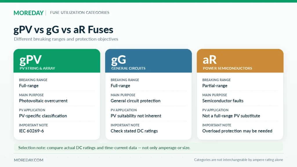
Comparison of Fuse Types
| Characteristic | gPV | gG | aR |
|---|---|---|---|
| Primary application | Photovoltaic strings and arrays | General electrical protection | Power semiconductor protection |
| Breaking-range designation | Full-range | Full-range | Partial-range |
| PV-specific characteristic | Yes | Not inherently | No |
| Typical protection focus | PV overcurrent and fault conditions | General circuit overload and short circuit | Semiconductor short-circuit protection |
| DC suitability | Defined by product DC ratings | Must be explicitly verified | Must be explicitly verified |
| Standard/category basis | IEC 60269-6 | IEC 60269 general/application requirements | Applicable semiconductor fuse requirements |
gPV vs gG Fuse
The gG utilization category is associated with general-purpose circuit protection.
Both gPV and gG are full-range categories, but their intended applications and operating characteristics differ.
A gG fuse may have a manufacturer-specified DC rating. Therefore, it would be incorrect to claim that all gG fuses are AC-only.
However, a DC-rated gG fuse does not automatically satisfy the PV-specific requirements of IEC 60269-6.
For PV string protection, the selected fuse should have the appropriate PV protection characteristics and supporting documentation.
gPV vs aR Fuse
An aR fuse is associated with high-speed semiconductor protection.
The letter “a” identifies a partial-range breaking-capacity fuse.
Such devices are designed for particular fault-current ranges and may require separate overload protection.
They are not directly equivalent to full-range gPV fuse links.
While both categories can be used in equipment associated with power conversion, the specific protection objectives differ.
For example, a semiconductor fuse intended to protect an inverter power module should not automatically be substituted for a PV string fuse.
Can a General DC Fuse Replace a gPV Fuse?
Only where the proposed replacement is explicitly suitable for the circuit and satisfies the applicable protection requirements.
Matching these three values is not sufficient by itself:
- Rated current.
- Rated DC voltage.
- Physical dimensions.
The replacement’s time-current behavior, breaking range, application rating, and supporting documentation must also be assessed.
For photovoltaic string circuits requiring a gPV fuse, replacing it with an unrelated general-purpose fuse can compromise the intended protection.
Key gPV Fuse Specifications Engineers Should Check
When evaluating a photovoltaic fuse datasheet, engineers should review the complete set of operating characteristics rather than selecting a product by rated current alone.
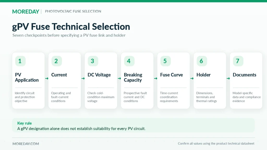
Rated DC Voltage
The fuse’s voltage rating must be suitable for the maximum voltage it may be required to interrupt.
In photovoltaic systems, the string open-circuit voltage increases as temperature decreases.
Therefore, selecting a 1000V or 1500V fuse requires an assessment of the maximum system voltage under the relevant design conditions.
Rated Current and Time-Current Characteristics
The rated current must support normal circuit operation under the applicable environmental conditions while remaining compatible with the protection limits of the modules and conductors.
Time-current curves are particularly important when evaluating whether a fuse can interrupt a prospective overcurrent within an acceptable duration.
A numerical rated current alone does not describe this behavior.
Breaking Capacity
The rated breaking capacity must meet or exceed the prospective fault current under the specified circuit conditions.
DC voltage, circuit time constant, and product-specific performance limits may affect suitability.
Power Dissipation and Temperature
Fuses generate heat during normal operation because of their electrical resistance.
High ambient temperatures inside solar combiner boxes may reduce their permissible current-carrying capability.
Engineers should review the manufacturer’s temperature correction data, power-dissipation characteristics, and compatible fuse holder ratings.
Fuse Dimensions and Holder Compatibility
Common cylindrical PV fuse dimensions include:
- 10 × 38 mm
- 10 × 65 mm
- 10 × 85 mm
- 14 × 85 mm
Not every fuse in these dimensions has the same voltage rating or application characteristics.
A suitable holder must provide the necessary electrical connections, thermal performance, mechanical compatibility, and installation ratings.
Practical Specification Checklist
| Specification | Required Verification |
|---|---|
| Utilization category | gPV or other approved PV fuse characteristic |
| DC voltage | Suitable for maximum system voltage |
| Rated current | Compatible with normal operation and protection limits |
| Breaking capacity | Suitable for available fault current |
| Time-current characteristics | Suitable for the intended protection function |
| Fuse dimensions | Compatible with the selected holder |
| Temperature performance | Appropriate for enclosure and installation conditions |
| Standards documentation | Correct IEC/UL evidence for the actual model |
For a detailed explanation of current and voltage selection, see How to Size a Solar PV Fuse: Current, Voltage & Calculation Examples.
Where Are gPV Fuse Links Used?
gPV fuse links are primarily associated with photovoltaic array protection.
Their application depends on the circuit configuration and the equipment requiring protection.
PV String Protection
In arrays containing parallel strings, a faulted string may receive current contributions from other strings.
A properly selected gPV fuse link can interrupt qualifying reverse-current faults and help protect the affected string and its wiring.
However, not every PV string requires its own fuse.
The need depends on available fault current, module limitations, conductor ratings, and applicable design standards.
For a detailed explanation, read When Are String Fuses Required in Solar PV Systems?.
Solar Combiner Boxes
PV string fuses are commonly installed within solar DC combiner boxes.
These assemblies combine multiple string inputs and may incorporate fuse holders, surge protective devices, switching equipment, and output terminals.
The fuse links provide overcurrent protection for the circuits specified by the electrical design.
Their presence does not eliminate the need for any other protective or switching functions required by the installation.
PV Sub-Array and Array Protection
Larger PV systems may contain additional combining and distribution stages.
At these locations, fuse links can be used to protect array or sub-array circuits against applicable overcurrent conditions.
The selected devices may have different current ratings, dimensions, and operating requirements from individual string fuses.
Are gPV Fuses Suitable for Battery Storage Systems?
Not automatically.
A battery can supply substantially higher prospective short-circuit currents than a typical photovoltaic string.
Battery circuits may also have different electrical time constants and coordination requirements.
A gPV rating alone does not establish suitability for battery energy storage protection.
A battery-specific fuse or another protective device with verified ratings may be required.
Similarly, gPV fuse links should not automatically be treated as adequate protection for inverter semiconductor components or internal DC-link capacitors.
These applications require separate engineering assessment.
MOREDAY gPV Fuse Solutions and Product Selection
MOREDAY provides DC fuse links and fuse holders for photovoltaic protection applications, including product families intended for 1000V and 1500V DC systems.
The available range includes cylindrical fuse links and DIN-rail-mounted holders suitable for different PV equipment configurations.
MOREDAY DC Fuse Link Range
The MOREDAY DC Fuse Link 1000V/1500V product family is presented for solar PV applications with reference to IEC 60269-6.
When preparing project specifications, the exact fuse model and its applicable technical documentation should be confirmed.
In addition to current and voltage ratings, procurement teams should request the relevant breaking capacity, operating characteristics, drawings, and compliance documents.
Compatible Fuse Holder Options
MOREDAY also offers products including:
- MDPV-30 1000V DC Fuse Holder — a DIN-rail fuse holder family for 10 × 38 mm fuse links.
- MDPV-32 1500V DC Fuse Holder — a DIN-rail fuse holder family for 10 × 85 mm fuse links.
The selected holder must be compatible with the actual fuse link.
Its voltage, current, thermal, and installation ratings must be verified independently of the fuse-link markings.
Documentation for Engineering and Procurement
For EPC contractors, distributors, and OEM customers, a complete fuse specification should include:
System voltage → Module data → Required fuse characteristic → Rated current → Breaking capacity → Fuse dimensions → Compatible holder → Applicable standards
Where a particular certification or listing is required, the supporting evidence should identify the corresponding model or certified product family.
An IEC standard reference, CE marking, or generic product description should not be treated as equivalent to a verified third-party certificate.
Find the Right PV Fuse Components
Explore the MOREDAY DC Fuse Product Range to review available photovoltaic fuse links, holders, and related protection equipment.
For a project-specific recommendation, provide the PV module datasheet, string configuration, system voltage, prospective fault-current conditions, and required technical standards.
Conclusion
A gPV fuse is a photovoltaic-specific fuse link designed to provide full-range DC overcurrent protection within its defined operating range.
Its distinguishing feature is not simply a high DC voltage rating. The gPV utilization category identifies fuse characteristics intended to address the electrical behavior of photovoltaic strings and arrays, including relevant low-overcurrent fault conditions.
IEC 60269-6 establishes the supplementary requirements for these fuse links, while PV array design standards determine how overcurrent protection should be incorporated into an installation.
Selecting a suitable gPV fuse requires checking its current rating, DC voltage, breaking capacity, time-current characteristics, and compatibility with the chosen holder.
For reliable solar PV protection, the complete electrical design and actual product documentation must guide the final selection.