

Uncategorized
A solar combiner box fuse must be selected according to the PV circuit’s overcurrent protection requirements, maximum DC voltage, current rating, breaking capacity, and compatible fuse holder. Choosing the correct fuse is essential for protecting PV strings and associated wiring from qualifying fault currents, particularly when multiple strings are connected in parallel.
However, selecting a fuse for a solar combiner box involves more than matching its ampere rating to the module’s short-circuit current. Engineers must also consider the number of strings, potential reverse-current paths, internal heat dissipation, conductor ratings, and the overall protection arrangement.
This guide explains how to select photovoltaic fuses for DC combiner boxes, where they should be installed, how they interact with other protective devices, and what to verify when specifying a complete combiner box assembly.
What Do Fuses Do in a Solar Combiner Box?
A solar combiner box connects multiple photovoltaic strings to one or more common DC output circuits.
Depending on the system design, it may contain individual string fuses, DC disconnecting devices, surge protective devices, terminals, and current-monitoring equipment.
The main purpose of a solar combiner box fuse is to interrupt qualifying overcurrent faults in the circuit it is designed to protect.
String Fuse Protection
When several PV strings are connected in parallel, a fault in one string may allow current from the remaining strings to flow into the faulted branch.
This reverse-current condition can exceed the affected module’s maximum permitted overcurrent protection rating or the current-carrying capacity of its conductors.
Where required by the electrical design, a properly selected gPV fuse can help interrupt such currents.
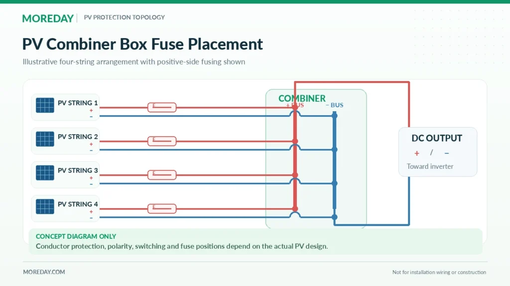
A typical conceptual arrangement is:
PV strings → Individual string fuse positions → Common DC busbars → DC output circuit → Inverter
The actual positive and negative conductor arrangements, switching devices, and protective-device locations depend on the system design.
String Fuses vs Array Output Protection
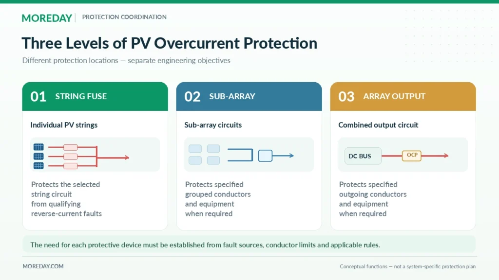
String protection and array output protection are not identical.
| Protection Location | Typical Purpose | Main Design Consideration |
|---|---|---|
| Individual string circuit | Protects against qualifying reverse-current or other overcurrent faults | Module limits, string current, and other current sources |
| Sub-array circuit | Protects specified sub-array conductors and equipment | Combined current, conductor ratings, and fault-current contributions |
| Array output circuit | Protects specified outgoing conductors and equipment where required | Total circuit current and available fault current |
| SPD backup protection | Provides protection or disconnection where specified by the SPD manufacturer | SPD coordination requirements and applicable ratings |
A fuse installed on one string cannot automatically be assumed to protect every downstream conductor or the entire array output.
Similarly, the presence of an output circuit breaker does not necessarily eliminate the requirement for individual string protection.
Fuse Link vs Fuse Holder
The fuse link contains the element that melts and interrupts overcurrent.
The fuse holder provides the mounting, contact, and connection interface.
Both components must be compatible with the intended voltage, current, installation temperature, and mechanical configuration.
A holder’s rated current or stated compatibility with a particular breaking-capacity fuse does not mean the empty holder independently interrupts that fault current.
For a broader introduction, see What Is a DC Combiner Box in a Solar PV System?.
When Are String Fuses Required in a Combiner Box?
Not every solar combiner box requires individual fuses on every string input.
The need for overcurrent protection depends on the available fault current, the PV module’s permitted overcurrent protection rating, conductor ampacity, and the applicable electrical design requirements.
Assess Parallel String Reverse Current
Consider four identical PV strings connected in parallel.
Assume:
- Each string has an Isc of 13A at Standard Test Conditions (STC).
- The PV modules have a maximum series fuse rating of 25A.
- No additional backfeed sources are included in this preliminary example.
If one string becomes faulted, the remaining three strings may contribute current to the affected branch.
A simplified estimate is:
Ireverse ≈ (Np − 1) × Isc
Therefore:
Ireverse ≈ (4 − 1) × 13A
Ireverse ≈ 39A
The estimated 39A contribution exceeds the hypothetical module’s 25A maximum series fuse rating.
This indicates that the string protection requirement must be addressed.
However, the estimate is based on STC current and does not replace the relevant design-standard calculation. Higher irradiance, bifacial generation, connected equipment, and other fault sources may change the actual result.
Why the Number of Strings Is Not a Universal Rule
It is common to encounter simplified recommendations such as “always install string fuses when three or more strings are connected in parallel.”
Although this may be a useful initial warning for certain conventional systems, it is not a universal design rule.
Some configurations can operate without dedicated string overcurrent devices when the applicable standards permit this and the modules, conductors, and equipment remain adequately protected.
Other systems may require protection with fewer parallel strings because of additional fault-current sources or equipment limitations.
The correct decision must be based on the actual circuit.
For a detailed explanation of these conditions, see When Are String Fuses Required in Solar PV Systems?.
When Output Circuit Fuses May Be Needed
The outgoing circuit carries the combined current from the connected strings.
Its conductors and components must be appropriately rated for the maximum expected circuit current and relevant fault conditions.
Where an output fuse or another overcurrent protective device is required, its position and rating must reflect the fault-current sources and the protection objective.
An outgoing protective device should not automatically be specified merely because several strings enter a combiner box.
The design must establish which circuit requires protection and whether the selected device can provide that protection.
How to Select the Right gPV Fuse for a Solar Combiner Box
After establishing the protection requirement, the next step is to select a suitable fuse link.
For conventional photovoltaic string overcurrent protection, gPV fuse links are commonly specified because their characteristics are intended for PV applications.
Choose the Appropriate Fuse Characteristic
The gPV utilization category identifies fuse links with characteristics defined for photovoltaic protection under IEC 60269-6.
PV fault currents can be comparatively low relative to those supplied by conventional electrical distribution networks.
The selected fuse must therefore be suitable for the relevant fault-current range, not simply for a high short-circuit current.
A general-purpose fuse should not automatically be substituted for a gPV fuse based only on identical current and voltage markings.
Verify the Rated DC Voltage
The fuse’s rated voltage must be suitable for the maximum voltage it may need to withstand or interrupt.
PV module open-circuit voltage increases as cell temperature decreases.
For this reason, the maximum string voltage must be calculated using the module datasheet, the minimum design temperature, and the relevant installation requirements.
For example, a system described as a 1000V PV installation may operate at a substantially lower voltage during normal power generation.
Nevertheless, the fuse must be selected for the applicable maximum voltage, not merely the normal operating voltage.
For higher-voltage PV installations, 1500V-rated equipment may be required.
The fuse link, holder, and other connected components must all be appropriately rated.
Select the Rated Current
The fuse current rating must satisfy the relevant normal-current carrying and overcurrent protection requirements.
Review the following information:
| Parameter | Selection Purpose |
|---|---|
| Module Isc | Determines the starting current for the design calculation |
| Maximum series fuse rating | Establishes the module’s specified overcurrent protection limit |
| Expected circuit current | Determines the required operating current capacity |
| Conductor ampacity | Ensures compatibility with cable protection requirements |
| Fuse temperature correction | Accounts for installation and ambient conditions |
| Time-current characteristics | Determines the fuse’s response to relevant overcurrent conditions |
The correct calculation depends on the applicable electrical rules and equipment configuration.
For conventional U.S. PV circuit applications, NEC-based sizing methods may use successive 125% factors under specified conditions.
However, 1.56 × Isc must not be applied automatically to every IEC-based design or every type of PV circuit.
For the detailed calculations, see How to Size a Solar PV Fuse: Current, Voltage & Calculation Examples.
Verify Breaking Capacity and Operating Characteristics
The selected fuse must have sufficient rated breaking capacity for the prospective fault current at the applicable DC voltage and specified operating conditions.
Its time-current characteristics must also be suitable for the protected equipment.
For example, if a PV string fuse has a rated current of 25A, this does not mean it will immediately open at 26A or 39A.
Its response time depends on the fault current and the fuse’s operating characteristics.
The engineering assessment must consider the fuse’s actual published data and the protected equipment’s limitations.
Check Fuse Link Dimensions
Common cylindrical PV fuse-link sizes include:
- 10 × 38 mm
- 10 × 65 mm
- 10 × 85 mm
- 14 × 85 mm
These dimensions are not universal voltage classifications.
A particular physical size may be available in different ratings or configurations depending on the manufacturer.
The exact fuse link must match the specified holder and applicable assembly documentation.
Where Should Fuses Be Installed Inside a PV Combiner Box?
Fuse placement should be based on the circuit’s fault-current paths and the equipment requiring protection.
In a conventional combiner arrangement, individual string protection devices are commonly located near the point where the strings connect to the common collection busbars.
This can allow a fuse to interrupt qualifying reverse current supplied from the parallel connection into the protected string.
String Fuse Placement
The fuse location should account for the connection between the individual string and the higher-current parallel source.
Where the applicable design rules require protection, the protective-device position must be appropriate for the actual source of overcurrent.
The required arrangement also depends on the lengths and ratings of conductors between the fuse and the collection point.
Positive and Negative Conductor Protection
PV systems can have different earthing and conductor arrangements.
The required number and location of fuses depend on the adopted electrical rules and the protection architecture.
Some systems incorporate protection in both positive and negative conductors.
Other designs may permit a single appropriately located overcurrent protective device in a specified conductor when all relevant conditions are met.
Therefore, neither 1P nor 2P fuse arrangements should be declared universally correct for every PV combiner box.
Engineers must confirm polarity, earthing arrangement, fault-current paths, applicable standards, and equipment requirements.
Coordination with DC Disconnects
A DC disconnect switch performs a different function from a fuse.
The fuse interrupts specified overcurrent faults.
A suitably rated disconnect or switch-disconnector provides the isolation or switching functions defined by its product rating and system design.
An ordinary fuse holder should not be treated as a load-break switch unless the complete assembly is specifically rated for that duty.
Never assume that opening a fuse holder is a safe method of interrupting an energized PV circuit.
Coordination with Surge Protection Devices
A solar combiner box may contain DC surge protective devices (SPDs).
These devices help limit transient overvoltages caused by lightning-related events and switching disturbances.
They do not replace required string overcurrent protection.
Likewise, a PV string fuse does not automatically provide the backup disconnection or protection required for an SPD.
Where an SPD requires external backup protection, the arrangement must follow the SPD manufacturer’s specified requirements.
The relevant product standard for PV DC SPDs includes IEC 61643-31.
The selected SPD and its protective arrangement must be coordinated with the PV system voltage, fault-current conditions, and earthing system.
Fuse Holder Compatibility and Thermal Design
Combiner box fuse selection is not complete until the fuse link, holder, enclosure, terminals, and conductors have been evaluated together.
This is particularly important in outdoor PV equipment.
Fuse Holder Electrical Compatibility
A compatible holder must support the specified fuse link and installation conditions.
Check:
- Rated DC voltage.
- Rated current.
- Supported fuse-link dimensions and references.
- Contact arrangement.
- Number of poles.
- Terminal conductor sizes.
- Installation method.
- Applicable ambient-temperature limits.
MOREDAY provides examples such as the MDPV-30 1000V DC Fuse Holder and the MDPV-32 1500V DC Fuse Holder.
The exact fuse link and holder combination must be verified using model-specific documentation.
Temperature Rise Inside the Combiner Box
PV combiner boxes are often installed outdoors, where they are exposed to high ambient temperatures and solar radiation.
Heat can also accumulate inside the enclosure as current passes through fuse links, contacts, busbars, and other components.
Factors affecting thermal performance include:
- Number of installed fuse links.
- Fuse-link power dissipation.
- Continuous operating current.
- Ambient temperature and solar exposure.
- Spacing between protective devices.
- Contact resistance and terminal condition.
- Enclosure material and heat dissipation.
- Cable grouping and installation arrangement.
A fuse link that performs satisfactorily under reference conditions may require derating in a hot enclosure.
The holder may also have separate thermal restrictions.
Why Fuse Derating Matters
Consider a fuse rated at 25A.
If the actual manufacturer’s temperature correction information indicates a permissible current reduction at the installation temperature, the effective continuous current capacity may be lower than 25A.
The required correction must be obtained from the selected product’s technical documentation.
A generic temperature factor must not be applied to every manufacturer or fuse family.
If thermal correction makes the fuse unsuitable, increasing its ampere rating may not be an acceptable solution because the higher rating could exceed the PV module’s maximum series fuse limit.
The appropriate response may involve changing the enclosure design, device arrangement, cooling conditions, or selected protective equipment.
Enclosure and Wiring Design
A suitable combiner box should have sufficient space for the required components and wiring.
The design should account for:
- Cable entry and sealing.
- Appropriate insulation clearances.
- Terminal spacing.
- Conductor bending space.
- Heat dissipation.
- Equipment accessibility.
- Environmental exposure.
- Earthing and protective bonding.
Ingress protection ratings such as IP65 describe specified dust and water ingress resistance. They do not independently establish complete outdoor suitability, corrosion resistance, ultraviolet durability, or thermal performance.
The enclosure and its installed equipment must be assessed as a complete assembly.
Example: Fuse Selection for a Four-String Solar Combiner Box
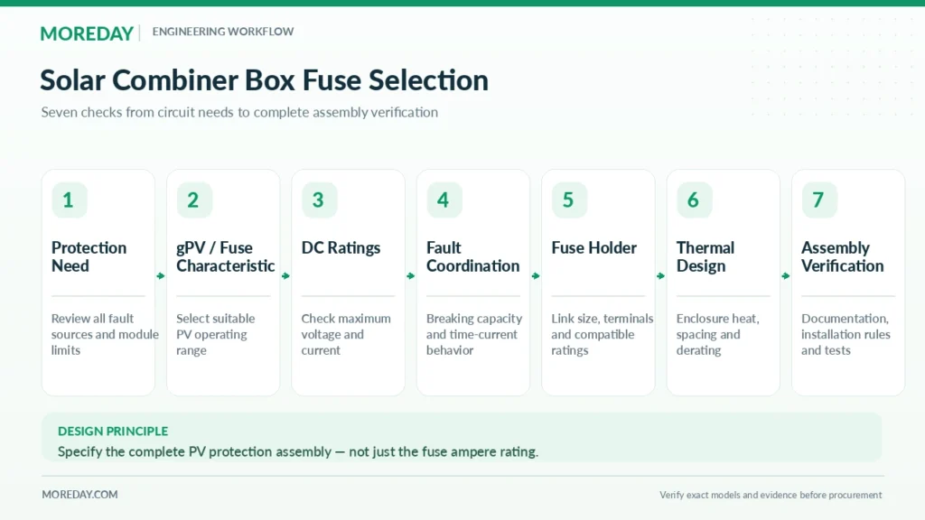
The following example demonstrates how the selection considerations fit together.
It is intended for preliminary engineering evaluation rather than as an approved installation design.
System Assumptions
| Parameter | Example Value |
|---|---|
| Parallel PV strings | 4 |
| Module Isc at STC | 13A |
| Module Imp at STC | 12A |
| Maximum module series fuse rating | 25A |
| Calculated maximum string voltage | 940V DC |
| Corrected string conductor ampacity | 30A, assumed |
| Other backfeed sources | None assumed |
| Proposed architecture | Four string inputs, one combined output |
Step 1: Assess the Reverse-Current Risk
If one string is faulted, the remaining three strings may contribute current through the common connection.
A simplified STC estimate is:
Ireverse ≈ (4 − 1) × 13A
Ireverse ≈ 39A
This exceeds the 25A module maximum series fuse rating, indicating a need to address string overcurrent protection.
The actual protection assessment must apply the appropriate current factors and consider all relevant sources.
Step 2: Evaluate a Candidate String Fuse
Using the conventional NEC-based sizing method described in the related fuse-sizing guide:
Preliminary minimum = 1.25 × 1.25 × 13A
Preliminary minimum = 20.31A
A 25A gPV fuse becomes a possible candidate for further review.
However, the proposed fuse still needs to pass the relevant temperature, fault-current interruption, time-current coordination, conductor, and module protection checks.
The fact that a 39A reverse-current estimate exceeds a 25A rating does not demonstrate that the fuse will operate within the required time.
Step 3: Check Maximum DC Voltage
The example assumes the maximum calculated string voltage is 940V DC.
A suitably specified 1000V DC-rated fuse meets this voltage threshold.
The fuse holder, disconnect equipment, SPD, and complete combiner assembly must also satisfy the maximum voltage requirements.
Step 4: Evaluate Combined Output Current
The combined maximum power operating current at STC is approximately:
Ioutput,mp = 4 × 12A = 48A
The combined short-circuit current at STC is approximately:
Isc,total = 4 × 13A = 52A
These values are useful starting points, but neither figure should be used as a final output conductor, terminal, busbar, or switching-device rating without applying the relevant design rules and operating factors.
Step 5: Confirm the Combiner Box Arrangement
The final design must specify:
| Component | Required Verification |
|---|---|
| Individual string fuses | Suitable current, voltage, characteristic and breaking ratings |
| Fuse holders | Correct electrical and physical compatibility |
| Collection busbars | Appropriate combined current capacity |
| Output conductors | Corrected ampacity and fault-current protection |
| DC disconnect | Correct voltage, current and switching or isolation ratings |
| DC SPD, if required | Voltage suitability, protection level and backup coordination |
| Enclosure | Adequate ingress protection, temperature-rise performance and space |
| Complete assembly | Appropriate design verification and project documentation |
The final decision also requires confirmation of whether one or both conductors need protective devices under the applicable installation rules.
Preliminary result: A four-input combiner box using properly selected 25A gPV string fuse candidates may be suitable for further engineering evaluation under the stated assumptions.
This does not establish a final approved fuse selection or complete combiner box rating.
Standards, MOREDAY Products and Procurement Checklist
A solar combiner box should be specified as an electrical assembly, not merely as a collection of separately rated components.
Relevant IEC and NEC Requirements
| Standard or Code | Main Relevance |
|---|---|
| IEC 60269-6 | Supplementary requirements for photovoltaic fuse links |
| IEC 62548-1 | PV array design, electrical protection and equipment selection |
| IEC 61439-8:2026 | Design and verification of photovoltaic electrical assemblies |
| IEC 61643-31 | Product requirements for PV DC surge protective devices |
| NEC Article 690 | PV system installation requirements for applicable U.S. projects |
IEC 61439-8:2026 establishes specific requirements for photovoltaic switchgear and controlgear assemblies, including relevant combiner box configurations.
It develops the PV assembly requirements previously addressed through annexes in IEC 61439-2:2020.
The edition adopted in a particular market, certification program, or project specification must be confirmed before asserting compliance.
The existence of these standards does not demonstrate that any particular MOREDAY product has been tested or certified to them.
MOREDAY Solar Combiner Box Solutions
MOREDAY offers solar DC fuse links, fuse holders, and combiner box equipment for photovoltaic protection applications.
Relevant product resources include:
- MOREDAY Solar Combiner Box Product Range
- MOREDAY DC Fuse Link 1000V/1500V
- MDPV-30 1000V DC Fuse Holder
- MDPV-32 1500V DC Fuse Holder
- MDXLD-16/1 PV DC Combiner Box
- MDXLD-24/1 PV DC Combiner Box
These product families illustrate available component and combiner-box configurations. Their final electrical ratings, protective-device arrangements, and supporting compliance documentation must be verified for the exact model and project.
Procurement Checklist for EPC and OEM Projects
When requesting a DC combiner box quotation, provide:
| Required Information | Project Detail |
|---|---|
| PV module model | Manufacturer and datasheet |
| Number of inputs | Required PV string circuits |
| Output configuration | One or more outgoing circuits |
| Maximum system voltage | Calculated maximum DC voltage |
| String current | Isc and relevant adjusted current |
| Module protection limit | Maximum series fuse rating |
| Protective devices | String fuses, output protection, SPD and switching requirements |
| Environmental conditions | Ambient temperature, solar exposure, enclosure location |
| Standards | Applicable IEC, NEC, UL or local requirements |
| Documentation | Wiring diagram, bill of materials, test evidence and technical datasheets |
The resulting specification should identify the exact protective components and their intended coordination rather than rely on a general description such as “1000V 4-in-1-out combiner box.”
Final Selection Recommendation
A suitable solar combiner box fuse is one that meets the electrical protection requirements of its intended circuit and operates correctly within a compatible, verified assembly.
Engineers should determine the need for string protection first, then check the proposed gPV fuse’s current rating, DC voltage, breaking capacity, time-current behavior, and environmental conditions.
The fuse holder, conductors, busbars, disconnecting equipment, and enclosure must also satisfy the complete design requirements.
For project-specific DC combiner box configurations, explore MOREDAY’s Solar Combiner Box Range or contact the MOREDAY technical team with your PV module specifications, string arrangement, and protection requirements.