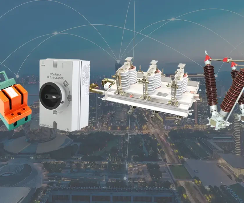
Distribution
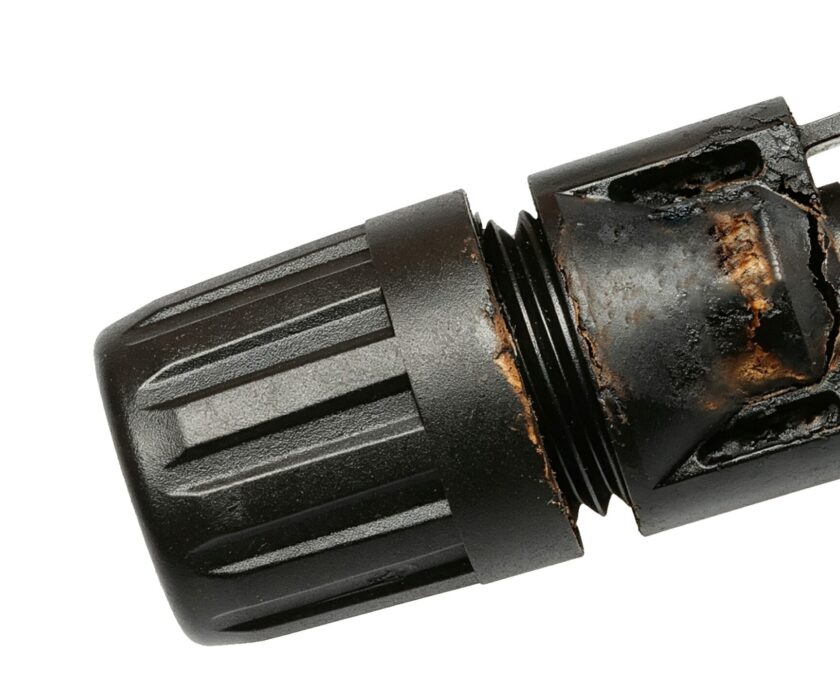
Sizing a DC circuit breaker solar PV is not guesswork, and it is not simply a matter of matching the breaker’s ampere rating to the panel’s current output. Get it wrong in one direction and you get chronic nuisance tripping every partly-cloudy afternoon. Get it wrong in the other direction and you have a breaker that holds during a fault, allowing a sustained arc to develop in a combiner box or junction enclosure until something burns.
This guide walks through the complete DC circuit breaker sizing process for solar PV systems — from string-level protection through combiner output and inverter disconnect — covering both IEC and NEC frameworks, multi-string parallel protection logic, voltage correction for temperature and altitude, and the derating factors that most sizing guides leave out.
DC Circuit Breaker Solar PV: Why Standard Sizing Fails?
Most DC circuits have a defined source impedance and a predictable fault current. Solar PV strings behave differently in two important ways that directly affect DC circuit breaker sizing:
PV strings are current-limited sources. A PV module cannot supply more than its short-circuit current (Isc) regardless of what happens downstream. This means fault currents in a single string are inherently bounded — they cannot spiral to the tens of kiloamps seen in battery or grid-connected fault scenarios. This is why string-level DC circuit breaker sizing is built around Isc rather than prospective short-circuit current from an unlimited source.
PV generation is a continuous duty load. Unlike a motor that starts and stops, or a lighting circuit that cycles, a PV string produces current continuously for the entire duration of sunlight hours — typically five to eight hours per day. Electrical codes define any load operating for three hours or longer as a continuous duty load, and continuous duty loads require a protective device rated at a higher multiple of the load current than intermittent loads. This is where the 125% derating factor originates.
Both of these characteristics — bounded Isc and continuous duty — shape every calculation in this guide.
Step 1: Identify the Key Parameters From the Module Datasheet
Before any calculation, you need four values from the PV module’s datasheet. These are always measured at Standard Test Conditions (STC): irradiance of 1000 W/m², cell temperature of 25°C, and AM 1.5 spectrum.
Isc — Short-Circuit Current: The current that flows when the module’s output terminals are shorted together. This is the maximum current the module can produce under any operating condition at STC. It is the starting point for all DC circuit breaker sizing calculations.
Impp — Maximum Power Point Current: The current at which the module produces maximum power. Always lower than Isc. Used for wire ampacity checks and inverter input sizing, but not for overcurrent protection device sizing — Isc is the correct basis for protection.
Voc — Open-Circuit Voltage: The voltage across the module’s terminals when no current flows. This is the maximum voltage the module can produce at STC, and it is the starting point for voltage rating calculations. Note that Voc increases as cell temperature decreases — cold weather, not hot weather, produces the highest system voltages.
Maximum Series Fuse Rating: The maximum overcurrent protection device rating recommended by the module manufacturer for a single module in a string. This value sets an upper bound on the string breaker rating and is a constraint you must not exceed.
Step 2: Calculate the Required Current Rating
For a Single String (Source Circuit)
The required DC circuit breaker current rating for a single PV string is:
Required In ≥ Isc × 1.25 (IEC framework)
or
Required In ≥ Isc × 1.56 (NEC 690.8 framework)
The difference between these two multipliers reflects a fundamental difference in how IEC and NEC approach solar PV protection:
IEC approach (IEC 60364-7-712): Applies a single 1.25× factor to Isc to account for the continuous duty nature of PV generation and for the possibility that irradiance may temporarily exceed the STC reference level (a phenomenon sometimes called high-irradiance or edge-of-cloud effect). The result is the minimum rated current of the overcurrent protection device.
NEC approach (NEC 690.8): Applies two sequential 1.25× factors. The first accounts for the possibility of irradiance exceeding STC conditions (producing current above Isc). The second accounts for continuous duty loading of the protection device itself. The combined factor is 1.25 × 1.25 = 1.5625, conventionally rounded to 1.56. This approach is mandated for installations in the United States and territories subject to NEC.
A critical point about double-counting: Once you have applied the 1.56 multiplier per NEC 690.8, you do not apply an additional 1.25× factor for continuous duty on top of the result. The continuous duty factor is already embedded in the 1.56 multiplier. Applying it twice is a common calculation error that leads to an oversized protection device, which in turn provides inadequate fault protection because its trip threshold is too high relative to the actual fault current.
Worked example:
- Module Isc = 10.2A
- IEC minimum In: 10.2 × 1.25 = 12.75A → select 16A (next standard size above)
- NEC minimum In: 10.2 × 1.56 = 15.91A → select 16A (next standard size above)
- Check against module maximum series fuse rating: if rated at 20A, both 16A selections comply
Always round up to the next standard device size — never down. Standard sizes typically run: 6, 10, 13, 16, 20, 25, 32, 40, 50, 63A.
For Multiple Parallel Strings (Array Circuit)
When two or more strings are connected in parallel at a combiner box, the protection requirements change — and this is where many designers make their most significant sizing error.
In a parallel array, each string can receive reverse current from the other strings if it develops a fault or a mismatch. This reverse current flows in the opposite direction to normal PV generation and can exceed the string’s Isc by a significant margin, potentially damaging modules and cabling.
When is string-level reverse current protection required?
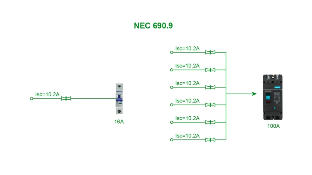
Both IEC 60364-7-712 and NEC 690.9 establish a threshold based on the number of parallel strings:
- If the number of parallel strings (N) is two or fewer, the reverse current that a faulted string could receive from the remaining strings generally does not exceed the module’s maximum series fuse rating. String-level overcurrent protection is typically not required.
- If N is three or more parallel strings, the reverse current can exceed the module’s series fuse rating. Individual string overcurrent protection is required at each string’s combiner input.
Calculating the combiner output (array-level) DC circuit breaker:
The combiner output breaker protects the cable between the combiner box and the inverter DC input. Its rating is based on the total array current:
Required combiner In ≥ (N × Isc) × 1.25 (IEC)
or
Required combiner In ≥ (N × Isc) × 1.56 (NEC)
However, this calculation often produces a result that requires a DC MCCB rather than a DC MCB — particularly in systems with four or more parallel strings using modern high-output modules. At this current level, breaking capacity becomes the critical selection parameter alongside rated current. Verify that the selected MCCB’s breaking capacity exceeds the prospective short-circuit current at the combiner output, which in a parallel array is no longer bounded by a single string’s Isc.
Worked example — 6-string array:
- Module Isc = 10.2A, 6 strings in parallel
- String-level DC MCB: 10.2 × 1.56 = 15.91A → 16A per string
- Combiner output: (6 × 10.2) × 1.56 = 95.47A → select 100A DC MCCB
- Check: fault current at combiner output from 5 remaining strings feeding a faulted string = 5 × 10.2 = 51A. A 100A MCCB comfortably contains this without nuisance tripping on normal array current.
Step 3: Calculate the Required Voltage Rating
The DC circuit breaker’s voltage rating must equal or exceed the maximum system voltage — and that maximum is not the Voc value from the datasheet. It must be corrected for temperature, because Voc increases as cell temperature falls below the STC reference of 25°C.
Series String Voltage
Uncorrected string Voc = N_series × Voc_module
Where N_series is the number of modules connected in series in one string.
Temperature Correction
At low temperatures — cold mornings, winter conditions, high-altitude sites — cell temperature can fall well below 25°C, causing Voc to rise above the STC value. The maximum system voltage calculation must account for the lowest expected cell temperature at the installation site.
IEC method (IEC 60364-7-712, Annex A):
Uses a temperature coefficient provided on the module datasheet (βVoc, expressed as %/°C or mV/°C):
Vmax = N_series × Voc × [1 + βVoc × (Tmin − 25)]
Where Tmin is the lowest expected ambient temperature at the site (in °C). Note that for a negative βVoc (voltage decreases with increasing temperature), Tmin will be the most negative value you use, producing the highest Vmax.
NEC method (NEC Table 690.7):
Uses a correction factor table based on the lowest expected ambient temperature. For example, at a lowest ambient of −10°C, NEC Table 690.7 gives a correction factor of 1.25. The maximum system voltage is then:
Vmax = N_series × Voc × 1.25
Select a DC circuit breaker with a voltage rating ≥ Vmax. Common standard DC voltage ratings are 250V, 500V, 600V, 750V, 1000V, and 1500V DC. Always select the next standard rating above your calculated Vmax — never a device rated exactly at Vmax, as manufacturing tolerances and calculation uncertainties mean a marginal selection offers no safety buffer.
Worked example:
- 20 modules in series, Voc = 49.5V, βVoc = −0.29%/°C
- Tmin = −10°C
- Vmax = 20 × 49.5 × [1 + (−0.0029) × (−10 − 25)] = 990 × [1 + 0.1015] = 1090V
- Select a DC circuit breaker rated 1200V DC or 1500V DC
Step 4: Verify Breaking Capacity Against Prospective Fault Current
Breaking capacity (Icn or Icu) is the maximum fault current the DC circuit breaker can safely interrupt. For solar PV, this check is most critical at the combiner output and inverter disconnect level — not at the individual string level, where the PV source current limitation naturally bounds fault currents.
At the string level: The maximum fault current from a single string fault is bounded by Isc of that string plus reverse current from parallel strings. In most residential and small commercial systems, this remains within the 6–10 kA breaking capacity of standard DC MCBs.
At the combiner output: The available fault current is the sum of all parallel strings. For a 10-string array with Isc = 10A per string, the maximum reverse current into a fault is approximately 90A — far below the breaking capacity of any standard MCCB. However, if the combiner is also fed from a battery bank or grid connection, the fault current can be orders of magnitude higher. Always evaluate the actual source combination at each protection point.
At the inverter DC input disconnect: The inverter’s DC input capacitors can discharge into a fault at very high instantaneous currents. For large central inverters with significant capacitance, this discharge current can be substantial. Consult the inverter manufacturer’s specifications for the maximum prospective fault current at the DC input terminals and verify that the selected DC circuit breaker’s breaking capacity exceeds this value.
Step 5: Apply Environmental Derating Factors
Standard DC circuit breaker ratings are specified at 40°C ambient temperature. Solar PV installations regularly operate in conditions that require derating.
Temperature Derating
In rooftop combiner boxes, surface-mounted enclosures in direct sun, or desert installations, the internal enclosure temperature can reach 60–70°C or higher. The thermal trip mechanism of a DC MCB or MCCB responds to the temperature of its internal components — not to the external ambient alone, but strongly influenced by it.
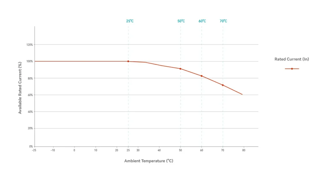
At elevated ambient temperatures, the effective current-carrying capacity of the DC circuit breaker decreases. The derating relationship is approximately:
- At 50°C: derate to approximately 90% of rated current
- At 60°C: derate to approximately 80–85% of rated current
- At 70°C: derate to approximately 70–75% of rated current
Specific derating curves are provided in the device manufacturer’s datasheet and should be used in preference to the general approximations above.
Practical application: If your calculation requires a device capable of carrying 25A continuously in a 60°C enclosure, and the manufacturer’s derating factor at 60°C is 0.82, the minimum nominal rated current is:
Required In = 25A ÷ 0.82 = 30.5A → select 32A
Without this correction, a 25A device in a 60°C enclosure will thermally trip under normal full-sun operating conditions — a fault that appears and disappears with the sun, is difficult to diagnose, and is entirely avoidable with correct sizing.
Altitude Derating
At altitudes above 2000 metres, reduced air density affects the arc extinction capability of DC circuit breakers. Thinner air supports arc propagation more readily than dense air at sea level, and the arc extinguishing mechanisms inside the breaker — which rely partly on the dielectric properties of air — perform less effectively.
The standard approach is to derate the voltage rating of the DC circuit breaker for high-altitude installations:
- Above 2000m: apply approximately 1% voltage derating per 100m of additional altitude
- At 3000m: a device rated 1000V DC at sea level should be treated as rated approximately 900V DC
This derating applies to the voltage rating only — not to the current rating. For installations at 2000m and below, no altitude derating is required.
Step 6: Check Against Cable Ampacity
The DC circuit breaker’s rated current must not exceed the ampacity of the cables it protects — after those cables have been derated for their own installation temperature and grouping conditions.
This is the fundamental protection logic: the DC circuit breaker protects the cable, not the load. If the breaker’s rated current exceeds the cable’s derated ampacity, the cable can overheat and fail before the breaker trips. This is a fire risk, not merely a compliance issue.
Cable ampacity calculation for PV DC circuits:
- Determine the cable’s base ampacity at the reference temperature (typically 30°C for IEC, or per NEC Table 310.15 for NEC installations).
- Apply temperature correction factor for the installation temperature.
- Apply grouping/bundling correction factor if multiple cables are run together.
- The resulting derated ampacity must be ≥ the DC circuit breaker’s rated current.
If the sizing calculation produces a breaker rating that exceeds the derated cable ampacity, the solution is to upsize the cable — not to accept a breaker that cannot protect it.
Putting It All Together: Sizing at Each Protection Point
A complete solar PV system has multiple DC protection points, each with its own sizing requirements.
String-Level DC MCB (Combiner Box Input)
- Current rating: Isc × 1.56 (NEC) or × 1.25 (IEC), rounded up to next standard size
- Voltage rating: ≥ Vmax of the string (temperature-corrected), next standard size above
- Breaking capacity: Standard DC MCB (6–10 kA) typically sufficient for single-string protection
- Trip curve: C-curve for virtually all residential and commercial PV applications
- Typical device: DC MCB, 1000V DC or 1500V DC rated, DIN rail mount
Combiner Output DC MCCB (Combiner to Inverter)
- Current rating: (N × Isc) × multiplier, derated for enclosure temperature
- Voltage rating: Same as string voltage (strings are in parallel — voltage does not add)
- Breaking capacity: Verify against total array fault current; consider inverter capacitor discharge
- Trip settings: Adjustable MCCB preferred for arrays with four or more strings
- Typical device: DC MCCB, current rating depends on array size
Inverter DC Input Disconnect
- Current rating: Per inverter manufacturer’s specified maximum DC input current × 1.25
- Voltage rating: ≥ maximum system voltage (same as string voltage)
- Breaking capacity: Verify against inverter DC fault current specification
- Function: Also serves as the maintenance disconnect for the inverter — must be lockable in the open position
- Typical device: DC MCCB or DC isolator with integral overcurrent protection
Battery DC Disconnect (Where BESS Is Included)
- Current rating: Battery bank maximum continuous discharge current × 1.25
- Voltage rating: ≥ battery bank maximum open-circuit voltage
- Breaking capacity: Battery fault currents are not PV-limited — can reach 10–50 kA or more for large lithium banks. This is a critical distinction. Use a DC MCCB with a verified breaking capacity against the battery’s maximum prospective fault current.
- Bidirectional rating: Battery systems require DC circuit breakers rated for current flow in both directions. Verify the selected device’s bidirectional capability explicitly.
Common Sizing Mistakes and How to Avoid Them
Applying the 1.25 continuous duty factor twice. The NEC 690.8 multiplier of 1.56 already includes the continuous duty factor. Applying 1.25× again to the 1.56× result produces an oversized device that cannot respond correctly to fault conditions near the threshold.
Sizing on Impp rather than Isc. The overcurrent protection device must be sized on short-circuit current, not maximum power point current. Impp is lower than Isc; using it underestimates the required protection level.
Ignoring temperature derating on the breaker. A 25A breaker in a 65°C enclosure is effectively a 20A breaker. System designers who ignore this consistently end up with nuisance tripping under full-sun conditions and replace breakers repeatedly before identifying the root cause.
Using an AC-rated breaker. The DC marking (−−−) and separate DC voltage rating are mandatory for solar PV applications. An AC breaker used in a DC circuit cannot reliably extinguish the DC arc under fault conditions. This is not a code technicality — it is a genuine fire hazard.
Assuming battery fault current behaves like PV fault current. PV sources are current-limited. Battery banks are not. A correctly sized string MCB is entirely wrong as a battery bank main disconnect. Always treat battery protection as a separate, higher-breaking-capacity calculation.
Summary: DC Circuit Breaker Sizing Checklist for Solar PV
Before finalising device selection, confirm each of the following:
- Current rating based on Isc (not Impp), with 1.25× (IEC) or 1.56× (NEC) multiplier
- 1.56× multiplier not double-counted for continuous duty
- Voltage rating based on temperature-corrected Voc, next standard size above Vmax
- Altitude derating applied where installation is above 2000m
- Temperature derating applied where enclosure ambient exceeds 40°C
- Breaking capacity verified against prospective fault current at each protection point
- String-level reverse current protection included where N ≥ 3 parallel strings
- C-curve trip characteristic confirmed for PV string circuits
- Selected breaker current rating does not exceed derated cable ampacity
- Device carries DC rating marking (−−−) and DC voltage rating ≥ Vmax
- Battery protection (where applicable) sized on battery fault current, not PV Isc
For a full overview of DC protection device types and selection principles, see our DC Circuit Breaker: All You Need to Know guide. For device type selection between MCB and MCCB, see DC MCB vs DC MCCB: What’s the Difference and How to Choose. For trip curve selection within the DC MCB range, see DC MCB Trip Curves B, C and D: How to Choose the Right One.
External references: IEC 60364-7-712 — Requirements for special installations: Solar photovoltaic (PV) power supply systems (iec.ch); NEC Article 690 — Solar Photovoltaic (PV) Systems (nfpa.org)