
Distribution
DC arc fault solar incidents are the leading cause of fires in photovoltaic installations — not inverter failures, not module degradation, not lightning strikes. An arc fault that begins as a loose terminal connection or a pinched cable can reach temperatures exceeding 5,000°C within milliseconds, and because DC current has no natural zero crossing to self-extinguish, the arc sustains itself and grows until it either destroys the conductor or ignites surrounding material.
What makes DC arc fault solar events particularly dangerous is that standard DC circuit breakers cannot detect them. A breaker trips on overcurrent — current exceeding its rated threshold. A series arc fault, by contrast, occurs at normal operating current levels. The current is not excessive; it is simply flowing across a gap rather than through a conductor. The breaker sees nothing unusual and stays closed while the arc burns.
This guide explains the physics of DC arc faults in solar systems, how series and parallel faults differ in their detection requirements, what AFCI and AFDD devices do that circuit breakers cannot, how to identify arc fault signatures in the field, and how to structure a prevention and response programme that addresses the problem before it becomes a fire.
Why DC Arc Faults Are Uniquely Dangerous in Solar PV Systems
Three characteristics of solar PV systems combine to make DC arc fault solar events more hazardous than arc faults in most other electrical systems.
Continuous generation. A PV array generates current as long as light falls on it. Unlike a building’s AC circuits, which can be isolated by opening a breaker at the distribution board, a PV string continues to produce voltage and current even after every switch in the system is open — as long as the panels are illuminated. A technician responding to a fire cannot simply “turn off” the solar panels. The source of the arc fault remains energised until the panels are physically covered or until irradiance drops below the system’s minimum operating threshold. This characteristic makes every DC arc fault in a solar system a self-sustaining fire hazard that cannot be interrupted by conventional means.
High DC voltage. Modern solar strings operate at 600–1500V DC. At these voltages, the ionisation energy available to sustain an arc is substantial. The arc plasma, once established, can bridge larger gaps and withstand greater interruption attempts than arcs at lower voltages. A series arc fault on a 1000V DC string releases significantly more energy per unit time than the same fault on a 120V AC circuit.
Distributed cabling in difficult environments. PV array wiring spans rooftops, ground arrays, and conduit systems exposed to UV radiation, thermal cycling, mechanical stress from wind and vibration, wildlife damage, and human activity during installation and maintenance. Each metre of DC cable and each connector is a potential arc fault initiation point, and large arrays may have kilometres of DC wiring. The statistical probability of a fault initiation point increases with every connector crimped, every cable bend, and every year of UV exposure.
Two Types of DC Arc Fault Solar Events: Series vs Parallel
DC arc fault solar events are not all the same. The two fundamental arc fault types — series and parallel — have different physical origins, different signatures, and critically, different implications for the protection devices that can detect them.
Series Arc Faults
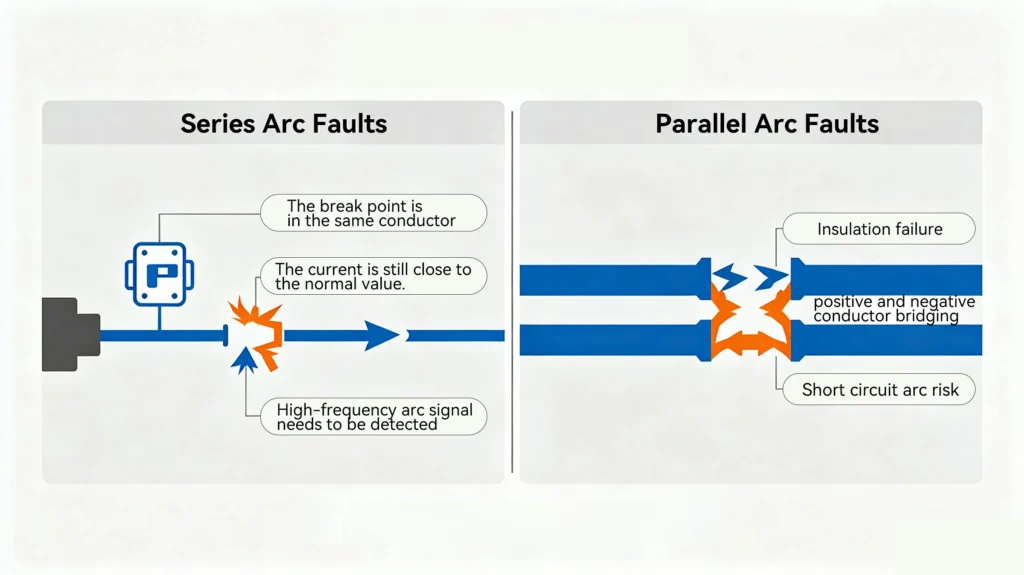
A series arc fault occurs when continuity is broken in a single conductor, forcing current to bridge the gap through ionised air rather than through the metal conductor. The current path remains the same — source to load through the string — but instead of passing through copper, part of the path passes through a plasma arc at the break point.
Common origins of series arc faults:
- Loose or improperly crimped MC4 connector that allows the contact to partially withdraw from the housing, creating a gap
- Wire terminal that has worked loose due to thermal cycling, vibration, or under-torqued installation
- Conductor damaged by nail, staple, or cable tie overtightening, where the mechanical damage creates a high-resistance point that eventually fails to an open circuit
- Connector or junction box contact corroded to the point of high resistance, which transitions to arc plasma under load
- Age-related insulation shrinkage that withdraws the conductor from its terminal contact
Why standard circuit breakers cannot detect series arc faults:
This is the most important point in understanding DC arc fault solar protection. In a series arc fault, the current flowing in the string is not significantly different from normal operating current. The arc introduces some additional resistance into the circuit, which reduces current slightly — but the breaker sees a current at or below its rated level and has no basis for tripping.
The arc fault produces two distinctive signatures that are invisible to a conventional breaker: a characteristic high-frequency signal superimposed on the DC current (typically in the 10–100 kHz range, produced by the periodic re-striking and partial extinction of the arc plasma), and localised heat at the fault point. Neither of these triggers a standard overcurrent device.
This is why NEC 690.11 and IEC 63027 mandate dedicated arc fault detection devices — specifically AFCI (Arc Fault Circuit Interrupter) in the US framework and AFDD (Arc Fault Detection Device) in the IEC framework — in addition to conventional overcurrent protection. The circuit breaker and the AFCI/AFDD serve different, complementary protection functions.
Parallel Arc Faults
A parallel arc fault occurs between two separate conductors — positive and negative — when insulation between them breaks down and current jumps the insulation barrier. The arc forms across the conductors rather than within a single conductor path.
Common origins of parallel arc faults:
- Cable insulation pinched between a roof fixture and structural element, with the insulation worn through over time
- Rodent or bird damage that strips insulation from adjacent conductors
- Moisture ingress into a junction box that creates a conductive path between positive and negative busbars
- Abrasion damage where positive and negative cables run in close proximity without adequate separation or conduit protection
How standard circuit breakers respond to parallel arc faults:
In a parallel arc fault, current from the source flows through the arc between the positive and negative conductors — a short circuit path of lower impedance than the intended load circuit. This produces a fault current higher than the normal operating current, and a correctly sized DC circuit breaker will detect this as an overcurrent and trip.
However, the breaker’s response time — milliseconds to tens of milliseconds at the magnetic trip threshold — may allow significant arc energy to accumulate before interruption. And if the parallel arc has impedance that limits the fault current to below the breaker’s magnetic trip threshold (an impedance-limited parallel arc), the breaker may respond only on the slower thermal element, allowing the arc to sustain for seconds before the breaker opens.
This is why overcurrent protection and arc fault detection are complementary: overcurrent protection addresses parallel arc faults and most short circuits; dedicated arc fault detection addresses the series arc faults that overcurrent devices fundamentally cannot detect.
AFCI and AFDD: What They Do That Circuit Breakers Cannot
How AFCI and AFDD Devices Detect Series Arcs
Both AFCI (NEC/UL framework) and AFDD (IEC framework) devices detect series arc faults by monitoring the high-frequency signal content of the DC circuit current. The characteristic arc fault signature — a broadband noise pattern in the 10–100 kHz range with specific time-domain characteristics — is superimposed on the normal DC operating current and is detectable with appropriate signal processing.
Modern AFCI/AFDD devices typically use a current transformer or Rogowski coil to capture the high-frequency current signal, followed by digital signal processing to distinguish the arc fault signature from other high-frequency sources in the PV system — including inverter switching harmonics, radio frequency interference, and the edge-of-cloud transients discussed in our DC MCB Trip Curves guide.
When the arc fault signature exceeds a threshold that indicates a sustained, growing arc, the AFCI/AFDD device signals the inverter to shut down and opens its integrated contactor or relay, disconnecting the affected circuit. Critically, this shutdown happens at normal current levels — the arc fault device does not wait for current to exceed the overcurrent threshold.
NEC 690.11: The US Requirement
NEC 690.11 requires listed DC arc fault circuit protection for PV systems installed on or in buildings in the United States. The requirement applies to the DC conductors of PV source circuits and PV output circuits. Listed devices under NEC 690.11 must:
- Detect series arc faults in the DC circuit at current levels below the overcurrent device trip threshold
- Annunciate the arc fault condition — the device must provide a visible or audible indication that an arc fault has been detected and the circuit has been de-energised
- Be listed under UL 1699B, the US standard for PV DC arc fault protection
The 2017 and 2020 editions of NEC 690.11 extended and clarified these requirements, and most modern string inverters for the US market include integrated AFCI functionality that satisfies NEC 690.11 without requiring a separate device.
IEC 63027: The International Framework
IEC 63027, first published in 2019, establishes the international requirements for Arc Fault Protection Equipment (AFPE) in PV systems. It focuses specifically on series arc faults and defines:
- Detection performance requirements — the device must detect a series arc fault within a specified time limit
- Test sequences using standardised arc fault generators to verify device performance
- Coordination requirements between AFPE and other protection devices in the PV system
IEC 63027 is increasingly referenced by national grid connection requirements in European and Asian markets. For projects in markets that have adopted IEC standards, confirm whether the applicable national grid code or installation standard references IEC 63027 and whether AFPE is mandatory or recommended for the project’s installation type.
Field Identification: Recognising DC Arc Fault Solar Signatures
Understanding the detection technology is useful. Being able to identify arc fault indicators in the field is essential — particularly for operations and maintenance teams responsible for existing installations without modern AFCI protection.
Thermal Imaging (Infrared Inspection)
Thermal imaging is the most effective field tool for identifying DC arc fault solar precursors before they escalate to sustained arc events. An infrared camera sensitive to temperature differences of 0.1°C or better can identify:
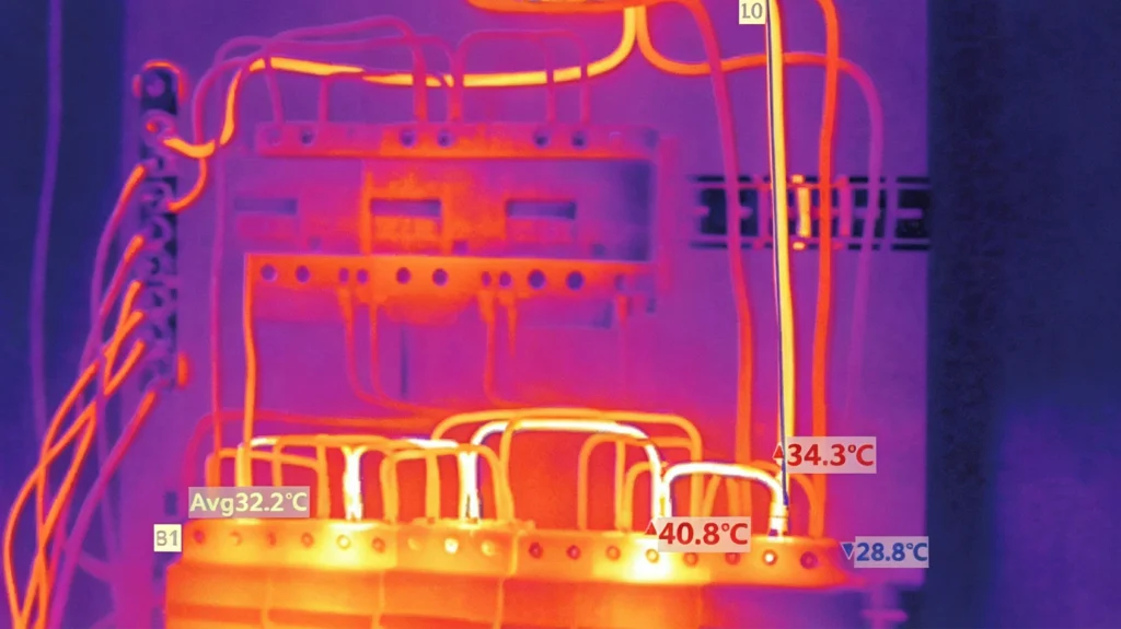
- Hot connectors: An MC4 connector running 10–20°C above adjacent connectors on the same string is experiencing elevated contact resistance — a reliable precursor to arc fault initiation. Normal connectors in the same operating conditions should be within 2–3°C of each other.
- Hot junction boxes: Elevated temperature at a junction box, particularly concentrated at one terminal rather than distributed across the box, indicates a resistive connection fault.
- Hot cable sections: A localised hot spot on a cable (as opposed to a gradual temperature gradient) may indicate internal conductor damage — a pinch or kink where strands have been broken and the reduced cross-section concentrates I²R heating.
When to perform thermal imaging: Thermal inspection is most useful under full-sun conditions with the system at or near full operating power — at low irradiance, the I²R heating from the operating current is insufficient to create the temperature differential needed to identify resistive faults. Mid-morning to early afternoon on a clear day, with the system at 80% or above rated power, is the optimal inspection window.
Thermal imaging frequency: Annual infrared inspection is the minimum standard for commercial systems. For residential systems, biennial inspection is widely recommended. Any time a significant wiring change has been made — new strings added, connectors replaced, cabling re-routed — a thermal inspection of the affected circuits within the first full-power operating day confirms the workmanship quality.
I-V Curve Tracing
An I-V curve tracer applies a controlled voltage sweep to a PV string or module and records the resulting current-voltage characteristic curve. A healthy string produces a characteristic curve whose shape matches the expected theoretical performance based on irradiance and temperature conditions. Deviations from the expected curve indicate:
- Series resistance increase: An upward tilt of the curve in the high-current region indicates increased series resistance — consistent with a high-resistance connection or partial arc damage to a conductor.
- Reduced fill factor: A “soft” knee in the I-V curve, where the transition from the current-dominated region to the voltage-dominated region is less sharp than expected, suggests cell-level mismatch or bypass diode activation — which may itself be caused by resistive heating from a high-resistance connection.
- Step changes in the curve: Abrupt steps in the I-V curve indicate bypass diode activation in one or more modules, suggesting shading, damage, or mismatch severe enough to reverse-bias those cells.
I-V curve tracing is more time-intensive than thermal imaging but provides quantitative data that thermal imaging cannot — specifically, the magnitude of series resistance increase, which allows resistive connections to be ranked by severity and prioritised for repair.
Visual Inspection for Arc Fault Precursors
Physical inspection remains valuable even in an era of remote monitoring and smart devices. Key indicators to look for:
- Discoloured or melted connector housings: MC4 connectors with brown, black, or deformed housings indicate past or ongoing arc fault activity. Replace immediately — a connector that has experienced arcing has damaged internal contacts that will arc again.
- Cable insulation damage: UV cracking, abrasion, pinch marks, or melted insulation sections indicate locations where insulation integrity is compromised and parallel arc fault risk is elevated.
- Moisture at connectors or junction boxes: Water ingress paths provide conductive paths between positive and negative conductors and accelerate corrosion of contacts. Inspect sealed connectors for cracked boots and junction boxes for water marks or corrosion products.
- Rodent damage: Cable sections routed at or near ground level are vulnerable to rodent gnawing. Damage is often not visible externally on bundled cables but can be identified by thermal imaging under load.
Prevention: Reducing DC Arc Fault Solar Risk at Installation
The most effective arc fault prevention programme begins before a single cable is pulled. The majority of DC arc fault solar events trace back to installation workmanship — not equipment failure, not environmental degradation, but decisions made during the installation itself.
Connector Quality and Compatibility
MC4 connectors from different manufacturers may appear compatible but have different contact geometry, locking mechanisms, and weatherseal designs. Mixing connector brands — even within the same project — is a recognised arc fault risk. IEC 62852 governs connector compatibility, but testing under the standard does not guarantee interoperability between all products that pass it. The safest approach is to use a single connector brand throughout a project, sourced from the same batch where possible.
Crimping is the other critical workmanship variable. An MC4 connector crimped with an incorrectly sized crimp die, with insufficient crimp force, or with a conductor that has been stripped to the wrong length will not achieve the designed contact resistance. A correctly crimped MC4 connection on a quality connector has a contact resistance below 1 mΩ. An incorrect crimp may produce 5–50 mΩ initially — high enough to cause measurable heating — and will worsen over thermal cycling.
Use a calibrated ratchet crimping tool with the die size specified by the connector manufacturer. Inspect every crimp using the pull-test method specified in IEC 60352-2 — a correctly crimped contact should withstand the specified extraction force without movement.
Cable Routing and Protection
Physical cable protection reduces the probability of insulation damage over the system’s life:
- Route positive and negative conductors of the same string together and keep them close — separated conductors are more likely to experience voltage stress across external insulation defects, increasing parallel arc fault risk
- Avoid tight bend radii — cables bent tighter than their minimum bend radius experience insulation stress that accelerates UV degradation and thermal fatigue
- Use UV-stable conduit or cable management where cables are exposed to direct sunlight and cannot be shaded by the module frame
- Keep DC cabling separated from AC cabling to avoid inductive coupling that can interfere with AFCI detection electronics
- Install rodent protection (metal conduit or armoured cable) for any section routed at ground level or through vegetation
For guidance on the broader wiring principles that underpin these practices, see our DC Circuit Breaker Wiring guide.
Terminal Torque and Connection Verification
As covered in the wiring guide, every DC circuit breaker wiring connection must be torqued to the manufacturer’s specification and verified by pull test. The same standard applies to every terminal in the DC circuit — junction box terminals, combiner box busbars, and inverter DC input terminals.
A torque verification log — a written record of the torque applied and verified for each connection during installation — is good practice for commercial systems and increasingly expected by commissioning engineers and insurers as part of the installation documentation package.
Response: What to Do When an Arc Fault Is Detected
Immediate Response to an AFCI/AFDD Trip
When an AFCI or AFDD device trips and de-energises a PV circuit:
1. Do not immediately reset the device. An AFCI/AFDD trip indicates that the device detected an arc fault signature — it is not a nuisance trip in the way that an overcurrent device might experience on a transient. Resetting without investigating the cause re-energises a circuit that has a documented fault and may re-establish the arc.
2. Isolate the affected circuit at the combiner box or string disconnect. Moreday’s DC Isolator provides a dedicated isolation point for this purpose — cover affected panels if the isolator is not accessible or if the arc fault location is unknown.
3. Perform a visual inspection of the affected string’s cabling and connectors from the panels to the combiner box input. Look for the physical indicators described above — discoloured connectors, damaged insulation, junction boxes with signs of heat.
4. Perform a thermal imaging scan of the affected circuit under load after temporary reconnection if the visual inspection is inconclusive. The arc fault point will typically show as the hottest point on the circuit.
5. Replace or repair the identified fault point. Do not re-use arced connectors — replace with new matched connectors, correctly crimped. If the fault point is a terminal, check for copper discolouration and carbon deposits, clean or replace the terminal, and re-torque to specification.
6. Perform an insulation resistance test of the repaired circuit before reconnecting to the AFCI/AFDD device. A reading below 1 MΩ indicates residual insulation damage that has not been fully addressed.
7. Reset and recommission. Reconnect to the AFCI/AFDD device and verify normal operation — no immediate re-trip and normal I-V curve tracing output.
Response to a Visible Arc or Fire
If a visible arc or fire is observed in a PV installation:
- Do not use water on an energised DC circuit. DC voltage at PV system levels (600–1500V) is lethal through a water stream. Use CO₂ or dry powder extinguishers rated for electrical fires.
- Cover the panels with opaque material if possible and safe — reducing irradiance reduces the fault current magnitude and may allow the arc to extinguish.
- Call emergency services immediately. Advise responding fire crews that the DC conductors from the PV array remain energised even after inverter shutdown, and that the hazardous voltage zone extends from the panels to the inverter DC input terminals.
- Do not open the inverter enclosure or any combiner box where an arc has been detected — energised conductors may be exposed.
Moreday DC Protection Products for Arc Fault Prevention
A properly protected solar DC circuit uses multiple protective layers working together. Moreday’s DC protection range provides the overcurrent protection components that form the foundation of this layered approach:
DC MCB range — C-curve string protection for solar PV combiner inputs, providing overcurrent protection for parallel arc faults and short circuits at the string level.
DC MCCB range — Adjustable protection for combiner outputs and main DC disconnects, with breaking capacity appropriate for the higher fault currents at aggregation points in the system.
DC Isolator — Manual isolation at string or combiner level for maintenance, commissioning, and arc fault response procedures.
SPD (Surge Protective Devices) — Transient overvoltage protection that prevents insulation stress events that can initiate parallel arc faults.
PV Combiner Box — Integrated combiner solutions with string-level fusing and DC protection devices pre-installed, reducing field wiring complexity and the associated workmanship fault risk.
These devices address the overcurrent and isolation functions. For series arc fault detection, ensure the inverter or a dedicated AFCI/AFDD device compliant with NEC 690.11 or IEC 63027 is included in the protection architecture.
Summary
DC arc fault solar events are the most significant fire risk in photovoltaic systems, and they cannot be adequately addressed by circuit breakers alone. Series arc faults — the most common arc fault type in PV systems — occur at normal operating current levels and are invisible to overcurrent protection devices. Dedicated AFCI or AFDD devices, combined with conventional DC circuit breakers for overcurrent and short-circuit protection, form the complete protection architecture.
Prevention begins at installation: matched and correctly crimped connectors, torqued terminals, protected cable routing, and documented commissioning procedures. Ongoing maintenance through annual thermal imaging and periodic I-V curve tracing identifies developing faults before they reach arc fault initiation. And a clear response protocol — starting with not resetting an AFCI trip without investigation — ensures that detected faults are properly resolved rather than masked.
For related reading, see our DC Circuit Breaker: All You Need to Know guide for DC protection fundamentals, DC Circuit Breaker Wiring: Polarity and 6 Costly Mistakes for the installation practices that prevent arc fault initiation, and DC Circuit Breaker Solar PV Sizing: 6 Critical Steps for the overcurrent protection sizing methodology that complements arc fault detection.
External references: NEC Article 690.11 — Arc-Fault Circuit Protection (nfpa.org); IEC 63027 — Arc-fault protection equipment for photovoltaic systems (iec.ch)