
Distribution
DC circuit breaker wiring is where most DC system failures actually originate — not in device selection, not in sizing, but in the moment a wire meets a terminal. A correctly specified, correctly rated DC circuit breaker installed with reversed polarity, an under-torqued terminal, or a mismatched cable can perform worse than a cheaper device wired correctly.
This guide covers DC circuit breaker wiring in full: the physics of why polarity matters more in DC than AC, the step-by-step connection process for both MCB and MCCB formats, conductor sizing and termination requirements, multi-pole series wiring for high-voltage systems, and the specific mistakes — with their failure mechanisms — that field engineers encounter most often.
Why DC Circuit Breaker Wiring Is More Demanding Than AC
Before getting into the practical steps, it is worth understanding why DC circuit breaker wiring carries consequences that AC wiring does not.
In an AC system, the current reverses direction 100 or 120 times per second. When a circuit breaker opens under fault conditions, the arc between the separating contacts extinguishes naturally at a current zero crossing — a moment of brief respite that allows the arc to cool and collapse. Wiring errors in AC systems — reversed line and load connections, for example — are often invisible in normal operation and only become problems at the moment of a fault.
In a DC system, there is no zero crossing. The arc formed when a DC circuit breaker opens under fault conditions must be extinguished entirely by the device’s internal mechanisms: arc splitter plates, magnetic blow-out coils, and arc chamber geometry. Many DC circuit breakers use permanent magnets specifically positioned to drive the arc into the arc chute. Those magnets are oriented for current flowing in a defined direction. Wire the device backwards, and the magnet drives the arc away from the chute and into the device’s body — which is plastic. The result is a sustained arc that destroys the breaker and can ignite the enclosure.
This is not a theoretical failure mode. It is the most common cause of catastrophic combiner box fires in solar PV installations. Every step in the DC circuit breaker wiring process is shaped by this fundamental difference between AC and DC arc physics.
Before You Start: Pre-Wiring Checks
Correct DC circuit breaker wiring begins before a single conductor is connected. These checks are not optional formalities — each one addresses a specific failure mode.
Verify the circuit is de-energized. Use a calibrated DC-rated multimeter to confirm zero voltage at every terminal you plan to connect. In a solar PV system, de-energizing means covering the panels or opening all upstream isolators — PV modules continue generating voltage in daylight regardless of downstream switch positions. A multimeter reading, not an assumption about switch state, is the only reliable confirmation.
Confirm the device’s DC rating markings. On the device’s nameplate, verify the DC voltage rating (marked with “—” or “DC”, for example 1000V DC) and the DC current rating. If the label shows only “VAC” or “~” with no DC marking, the device must not be used in the DC circuit regardless of how the ratings compare numerically.
Check the wiring diagram. Every DC circuit breaker ships with a wiring diagram showing terminal designations, polarity markings, and connection orientation. For DIN rail MCBs, the diagram is typically printed on the device or inside the packaging. For MCCBs, it is in the installation manual. Read it before connecting anything — do not rely on assumed terminal layouts from previous installations, as conventions vary between manufacturers and product families.
Identify current flow direction. In a PV string circuit, current flows from the panels toward the inverter — source on one side, load on the other. In a battery circuit, current is bidirectional. This distinction determines whether a polarized or non-polarized device is appropriate, and whether the polarity markings on the device define a required connection orientation.
Understanding Polarity Markings: What the Labels Actually Mean
DC circuit breaker wiring diagrams use several different notation systems for polarity and terminal orientation. Knowing how to read them prevents the most dangerous wiring mistake in DC systems.
Line and Load Terminals
Many DC circuit breakers — particularly DC MCCBs — mark their terminals as LINE (or L, or IN) and LOAD (or T, or OUT). These designations indicate:
- LINE terminal: Connect the conductor coming from the power source — the PV string, the battery bank output, or the upstream busbar.
- LOAD terminal: Connect the conductor going to the load — the inverter input, the next protection tier, or the downstream circuit.
In a polarized DC circuit breaker, the permanent magnets are oriented to assist arc extinction for current flowing from LINE to LOAD. Reversing this connection — source on LOAD, load on LINE — reverses the magnetic blow-out direction and defeats arc extinction under fault conditions.
Practical note: In a solar PV system, “LINE” is the panel side and “LOAD” is the inverter side. In a battery bank main disconnect, the convention may be less obvious — consult the device’s wiring diagram specifically, as some battery-side MCCBs are installed with the battery terminal on LOAD, depending on the protection coordination design.
Polarity Symbols: (+) and (−)
DC circuit breakers that interrupt a single conductor — typically the positive conductor in a grounded-negative system — mark their terminals with (+) for the source-side positive conductor and (−) for the negative return, or simply mark the pole that interrupts the positive conductor.
In a standard two-wire DC circuit with a grounded negative conductor, the DC circuit breaker is installed in the positive conductor only. The negative conductor passes through uninterrupted, connected to the negative busbar. The circuit breaker’s (+) terminal connects to the positive source; its output terminal connects to the positive load.
Exception: In ungrounded DC systems — common in solar PV systems designed to IEC 60364-7-712 — both the positive and negative conductors are ungrounded, and the DC circuit breaker must interrupt both conductors simultaneously. This requires a two-pole DC circuit breaker wired with the positive conductor on one pole and the negative conductor on the other. Single-pole interruption in an ungrounded system leaves one conductor energized after the breaker opens, creating a shock hazard.
Step-by-Step DC Circuit Breaker Wiring
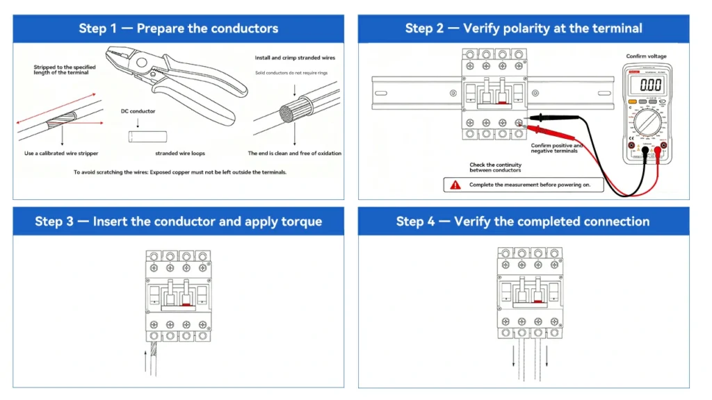
Step 1 — Prepare the conductors
Strip the conductor insulation to the length specified in the terminal manufacturer’s documentation — typically 10–14mm for DIN rail MCB screw terminals, and 15–20mm for MCCB lug connections. Use a calibrated wire stripper set to the conductor gauge to avoid nicking the conductor strands. A nicked conductor at a terminal point concentrates current and heat at the nick, accelerating fatigue and increasing resistance over time.
For stranded conductors at screw-type terminals, fit correctly sized ferrules (bootlace terminals) and crimp them with a ratchet crimping tool before insertion. Bare stranded wire in a screw terminal is subject to individual strands being cut or displaced by the screw, reducing the effective conductor cross-section at the connection point and increasing contact resistance.
For solid conductors, no ferrule is required. Ensure the stripped end is clean and free of oxidation — use fine sandpaper or a wire brush on aluminium conductors before insertion.
Step 2 — Verify polarity at the terminal
Before inserting any conductor, use a multimeter set to DC voltage to confirm:
- Which conductor is positive and which is negative
- The voltage between the conductors (confirming the circuit is or is not energized)
- Continuity between the conductor and its expected source/load terminal
This step is particularly important when working with pre-existing wiring where colour coding may not have been consistently applied, or on retrofit installations where the original installer’s practices are unknown.
Standard conductor colour conventions for DC circuits vary by region and standard. IEC 60446 designates red or brown for positive DC conductors and black or blue for negative; North American practice often uses red for positive and black for negative in low-voltage DC systems, and white for negative at higher voltages. Do not assume colour coding is correct — verify polarity with a meter before connecting.
Step 3 — Insert the conductor and apply torque
Insert the conductor into the terminal to the full depth indicated by the terminal’s insertion mark or until the stripped conductor end is fully inside the terminal body with no bare copper exposed outside.
Apply the torque specified in the manufacturer’s documentation using a calibrated torque screwdriver or torque wrench. This is not a step where “reasonably tight” is an acceptable standard.
Why torque specification is a safety requirement, not a preference:
DC circuit breaker wiring connections that are under-torqued create a high-resistance interface between the conductor and the terminal contact surface. As current flows through this interface, I²R heating occurs — the resistance multiplied by the square of the current produces heat in direct proportion to current squared. This heat causes thermal expansion of the metal components, which slightly loosens the connection further. The loosening increases resistance, which increases heating, which causes more loosening. This progressive failure mechanism — thermal cycling loosening — is self-accelerating and ultimately produces a connection hot enough to carbonise insulation, ignite adjacent materials, or cause the conductor to arc inside the terminal.
The manufacturer’s torque specification is determined by testing to confirm that the connection maintains adequate contact force through the thermal cycling that occurs over the device’s service life. Under-torquing places the connection outside the tested performance envelope from the first operating cycle.
Typical torque values for DC MCB screw terminals: 2–3 Nm for 1.5–6mm² conductors, 3–4 Nm for 10–16mm² conductors. DC MCCB lug connections: 8–25 Nm depending on conductor size and terminal design. Always use the value in the device’s specific documentation, not a generic estimate.
Step 4 — Verify the completed connection
After connecting all conductors and before energising the circuit, perform a final visual and mechanical check:
- No bare conductor visible outside the terminal body
- Cable insulation begins at or close to the terminal entry point — a gap of more than a few millimetres suggests the conductor is not fully inserted
- All conductors are correctly identified and connected to the intended terminals
- The device’s trip lever is in the OFF (open) position
- No tools, loose conductors, or foreign objects inside the enclosure
Perform a conductor pull test by hand — apply moderate pull force to each conductor at the terminal. A correctly torqued connection will not move. A conductor that pulls free or rotates indicates inadequate torque — re-insert, check for damage, and re-torque.
Conductor Sizing: The Protection Logic
DC circuit breaker wiring is not complete until the relationship between conductor size and device rating is verified. This relationship is the fundamental logic of overcurrent protection: the circuit breaker protects the conductor, not the load.
The DC circuit breaker’s rated current must not exceed the conductor’s derated current-carrying capacity. If the breaker rating is higher than the conductor’s capacity, the conductor can overheat and fail before the breaker trips — a fire risk that no amount of correct terminal torque can mitigate.
The derated conductor ampacity calculation:
- Determine the conductor’s base ampacity at the reference temperature from the applicable cable standard (IEC 60228 for IEC markets, NEC Table 310.15 for US installations).
- Apply a temperature correction factor for the installation ambient temperature. In rooftop combiner boxes and outdoor enclosures in direct sun, ambient temperatures frequently exceed 60°C — at which standard 90°C-rated cable is derated to approximately 71% of its base ampacity.
- Apply a grouping factor if multiple cables are bundled together in conduit or cable trays. Bundled cables cannot dissipate heat individually, reducing each cable’s effective capacity. IEC 60364-5-52 provides grouping correction factors; NEC Table 310.15(C)(1) provides the equivalent for US installations.
- The resulting derated ampacity must be equal to or greater than the DC circuit breaker’s rated current.
Common error: Specifying cable size based on the circuit’s normal operating current without accounting for temperature and grouping derating. The result is cable that runs near or above its thermal limit continuously, degrading insulation over time and producing a slow-developing fire hazard that is difficult to trace to its cause.
Multi-Pole Series Wiring for High Voltage DC
Many DC circuit breakers achieve high voltage ratings — 1000V DC, 1500V DC — by connecting multiple poles in series internally or by requiring the installer to connect poles in series during installation. DC circuit breaker wiring in these configurations requires specific attention.
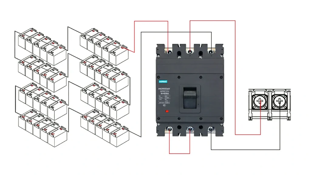
Internal Series Connection
Some DC MCBs rated for 1000V DC achieve this rating by connecting two poles in series internally at the factory. The device appears single-pole externally — one input terminal, one output terminal — but internally the current passes through two arc extinguishing chambers in series, with each chamber handling half the total voltage. The doubled arc voltage across two chambers enables reliable extinction at the full 1000V DC rating.
For this device type, the installer connects the circuit as a single-pole breaker — no special series wiring is required. The internal series connection is transparent to the installer.
External Series Connection (Two-Pole for High DC Voltage)
Other DC circuit breakers achieve high voltage ratings by connecting two poles in series externally — the output of pole 1 connects to the input of pole 2 via a jumper bar or bus link, and the circuit feeds into the input of pole 1 and out of the output of pole 2. The two arc extinguishing chambers are now in series in the external circuit.
DC circuit breaker wiring for external series connection:
- The jumper bar between poles must be rated for the full circuit current — use the manufacturer’s specified jumper bar, not a field-fabricated link
- The polarity orientation must be consistent across both poles — both poles must carry current in the same direction through the device
- The device’s label will show the series DC voltage rating (e.g., 2P = 1000V DC) only when poles are correctly connected in series; single-pole operation would be rated at half this voltage
- Never connect the two poles in parallel — paralleling poles of a circuit breaker does not double the current rating and creates unequal current sharing that can damage the device
Three-Pole and Four-Pole DC Configurations
Three-pole and four-pole DC MCCBs may use all poles in series (for maximum voltage rating), or may dedicate poles to specific functions (e.g., two poles in series for the positive conductor, one pole for the negative conductor in a specific system architecture). Always follow the manufacturer’s connection diagram exactly — the configuration is not always intuitive from the terminal layout alone.
Grounding and Enclosure Bonding
DC circuit breaker wiring is incomplete without correctly bonding the enclosure and equipment grounding conductors.
The DC circuit breaker’s metal enclosure or DIN rail must be connected to the system protective earth (PE). In most installations, the DIN rail itself is bonded to the enclosure earth bar, and a separate green/yellow PE conductor connects the enclosure to the system earth point.
Solar PV specific: IEC 60364-7-712 and NEC Article 690 have specific requirements for grounding DC circuits in PV systems, which differ between grounded and ungrounded system designs. In a grounded-negative system, the negative DC conductor is connected to earth at a defined system grounding point — the DC circuit breaker’s negative conductor path must accommodate this connection without creating ground loops. In an ungrounded (floating) system, neither the positive nor negative conductors are intentionally earthed, and ground fault detection equipment monitors for unintended earth faults.
Confirm the system grounding architecture before completing DC circuit breaker wiring and ensure the grounding connections are consistent with it.
Commissioning Tests After Wiring
Before energising any DC circuit with a newly wired breaker, perform the following sequence:
1. Insulation resistance test (megger test): With the DC circuit breaker in the open position, apply a DC test voltage (typically 500V DC for systems up to 1000V) between each active conductor and earth. A healthy insulation resistance reading is ≥1 MΩ per IEC 60364-6 (many authorities require much higher values for new installations — ≥ 1 GΩ is achievable and expected in new PV wiring). A low reading indicates damaged insulation, a wiring error, or a moisture ingress problem — resolve before energising.
2. Polarity confirmation: With the source energised and the DC circuit breaker in the open position, measure the voltage at the LINE terminals. Confirm the correct polarity and expected voltage. Then close the breaker and measure at the LOAD terminals — confirm the breaker passes voltage correctly in the closed position.
3. Continuity test: With the circuit de-energised and the breaker closed, confirm continuity through each pole from LINE to LOAD. With the breaker open, confirm no continuity — both confirming the contact opens fully.
4. Tripping test: Where test equipment permits, verify that the breaker trips at the expected overcurrent level. For most field installations, this is limited to a manual trip test (pressing the trip button or actuating the test function if provided), rather than a calibrated injection test. Full calibrated trip testing is performed at commissioning of large systems.
Common Wiring Mistakes and Their Failure Mechanisms
Reversed LINE/LOAD on a polarised device. The permanent magnets drive the arc into the device body rather than the arc chute. The device will likely survive normal operation but will be destroyed by the first significant fault current. The failure produces fire inside the enclosure.
Reversed positive/negative polarity. In systems with polarity-dependent protection (ground fault detectors, RCDs, BMS contactors), reversed polarity defeats the protection function. In polarised DC breakers, reversed polarity has the same effect as reversed LINE/LOAD — incorrect arc blow-out direction.
Under-torqued terminals. Creates thermal cycling loosening as described above. The failure is gradual, appears as unexplained heat at the terminal, and eventually produces a connection arc inside the terminal body. Often misdiagnosed as a device failure when the root cause is the connection.
Bare stranded wire in screw terminals without ferrules. Individual strands spread under the terminal screw, some are cut, and the effective conductor cross-section is reduced. The connection also tends to loosen over time as spread strands work their way out from under the screw. Ferrules are the correct solution — they are inexpensive and the installation time is negligible.
Cable size smaller than breaker rating. The conductor can overheat before the breaker trips. The breaker is protecting an open circuit rather than the cable. Correct the design — either upsize the cable to match the breaker rating, or downsize the breaker to match the cable’s derated ampacity.
Using AC-rated cable in DC applications without checking voltage rating. Some cable insulation systems are rated for different AC and DC voltages. AC voltage rating is based on RMS voltage; DC voltage rating must account for the absence of zero crossings and the steady-state stress on insulation. Verify that the cable’s DC voltage rating meets or exceeds the system DC voltage — not just the AC rating.
Summary
DC circuit breaker wiring requires closer attention to polarity, termination quality, and conductor sizing than equivalent AC installations — not because the physical process is more complex, but because the consequences of errors are more severe in DC systems where arc extinction cannot rely on natural current zero crossings.
The non-negotiables are: confirm polarity before connecting, connect LINE to source and LOAD to load on polarised devices, torque every terminal to specification with a calibrated tool, verify conductor ampacity against the breaker’s rated current after derating for temperature and grouping, and test insulation resistance before energising. Every other aspect of DC circuit breaker wiring builds on these five foundations.
For related guidance, see our DC Circuit Breaker: All You Need to Know guide for DC protection principles, DC MCB vs DC MCCB: What’s the Difference and How to Choose for device type selection, and DC Circuit Breaker Solar PV Sizing: 6 Critical Steps for sizing methodology that establishes the correct rated current before wiring begins.
External references: IEC 60364-5-54 — Selection and erection of electrical equipment: Earthing arrangements and protective conductors (iec.ch); IEC 60228 — Conductors of insulated cables (iec.ch)