
DistributionSolar
Pole count looks like the simplest spec on a DC MCB datasheet — until it’s the reason an installation fails inspection, or worse, the reason a fault path stays energized after the breaker has supposedly opened. The DC MCB 1P vs 2P vs 4P decision isn’t about how many circuits you’re protecting; it’s about which conductors are actually broken when the breaker trips, and that has a direct, code-relevant safety implication in DC systems that AC installers often carry over incorrectly.
This guide breaks down the real differences in the DC MCB 1P vs 2P vs 4P comparison, when each pole configuration is required rather than optional, and the mistake that shows up most often when breaker pole count is chosen by habit instead of by system design.
For the complete guide, see: DC Circuit Breaker: All You Need to Know
What “Pole” Actually Means on a DC MCB
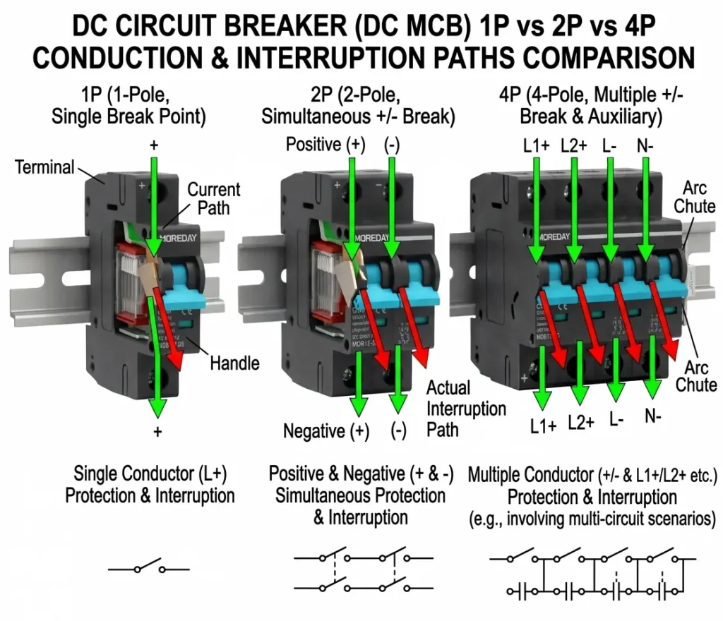
A pole is a separately switched contact inside the breaker. On an AC breaker, pole count usually maps to phases. On a DC MCB, it maps to something more specific: how many current-carrying conductors are mechanically opened at the same time, by the same handle, in a single trip event.
- 1P (single pole): breaks one conductor only — typically the positive or the negative leg of a DC circuit, not both.
- 2P (double pole): breaks both the positive and negative conductors simultaneously, using a common internal linkage so both poles open together, every time.
- 4P (four pole): breaks four conductors simultaneously — most often used where two independent DC circuits (two strings, or a string plus a parallel circuit) need to be isolated together under one handle, or where a neutral/auxiliary conductor must be switched alongside the main poles.
DC MCB 1P vs 2P vs 4P: Quick Comparison Table
| Criteria | 1P | 2P | 4P |
|---|---|---|---|
| Conductors broken per trip | 1 | 2 (both DC legs) | 4 (two circuits, or 2 legs + auxiliary) |
| Typical use case | Functionally grounded PV arrays where one leg is bonded to ground | Ungrounded (floating) PV arrays — most common modern default | Dual-string combiner boxes, split-bus battery systems |
| Grounding requirement | System must have a reliably grounded conductor | No grounding assumption required | Depends on the two circuits being switched |
| Code alignment | Only acceptable where local code permits single-pole disconnection | Aligns with codes requiring simultaneous disconnection of all current-carrying conductors | Used where a single isolation point covers two circuits at once |
| Relative cost | Lowest | Moderate | Highest |
| Panel space required | Smallest | Moderate | Largest |
DC MCB 1P vs 2P vs 4P: Why Grounding Scheme Decides the Answer
The single biggest factor in the DC MCB 1P vs 2P vs 4P decision isn’t current rating or panel space — it’s whether the DC system is grounded or ungrounded, because that determines which conductors can safely be left connected when the breaker trips.
In a functionally grounded PV array, one DC conductor is intentionally bonded to ground through the inverter or a grounding device. In that specific configuration, opening only the un-grounded conductor with a 1P breaker can be an acceptable, code-recognized disconnection method, because the grounded conductor is not considered a fault-current path in the same way.
In an ungrounded (floating) array — which is now the majority configuration in transformerless string inverter systems — neither DC conductor is bonded to ground. Opening only one leg with a 1P breaker leaves the other leg fully energized relative to ground. A technician who assumes the circuit is dead because “the breaker tripped” can still contact a live conductor. This is precisely why installation codes such as IEC 60364-7-712 for PV power supply systems, and NEC 690.13 in NFPA 70 in the US, require simultaneous disconnection of all current-carrying conductors for ungrounded PV source and output circuits — which in practice means a 2P DC MCB with common-trip poles, not a single 1P device.
When to Use a 1P DC MCB
- Only in systems with a confirmed, code-compliant grounded conductor, where local regulations explicitly permit single-pole disconnection.
- Low-voltage, low-risk auxiliary circuits where full simultaneous disconnection isn’t a safety requirement.
- Cost- and space-constrained designs where the grounding scheme has been verified to make 1P protection code-compliant — never assumed by default.
When to Use a 2P DC MCB
- Ungrounded (floating) PV strings and combiner circuits — the standard default for modern transformerless inverter systems.
- Anywhere the installation code requires simultaneous disconnection of both DC conductors, which is the majority case in current PV and BESS installations.
- Any circuit where a technician needs a guarantee that opening the breaker de-energizes the entire circuit, not just one leg of it.
When to Use a 4P DC MCB
- Dual-string or dual-circuit combiner boxes, where two independent PV strings (or a string plus a battery feed) need to be isolated together from a single handle for maintenance convenience.
- Split-bus battery storage configurations, where two separate DC buses must be de-energized simultaneously for safety during service.
- Panels where reducing the number of separate switching points (and therefore separate lockout/tagout steps) is a design priority.
Common Mistakes
Using two separate 1P breakers wired together instead of a true 2P common-trip device. Two 1P breakers on the same handle-tie hardware do not guarantee truly simultaneous internal tripping the way a factory 2P mechanism does — if one pole’s contacts weld or stick, the other can still open on its own, which defeats the purpose of requiring simultaneous disconnection in the first place.
Assuming an ungrounded array can use 1P protection to save cost. As covered above, this is the single most common code violation seen in DC MCB 1P vs 2P vs 4P selection, and it isn’t a minor paperwork issue — it’s a live-conductor safety hazard during what looks like a de-energized state.
Over-specifying 4P where 2P is sufficient. Using a 4-pole device to protect a single circuit adds unnecessary cost and panel space without a corresponding safety or functional benefit — 4P earns its place when it’s genuinely consolidating two circuits into one isolation point, not by default.
Not checking whether “2P” on a datasheet means common-trip or independently switched. Some manufacturers use “2P” loosely to describe two 1P mechanisms in a shared housing without a guaranteed common trip. Always confirm common-trip operation directly against the DC MCB’s technical datasheet before assuming code compliance.
FAQ
Is a 2P DC MCB always required for solar PV? Not universally, but it is required in the majority of modern installations, because most PV arrays today are ungrounded (floating), and codes covering ungrounded DC systems require simultaneous disconnection of all current-carrying conductors. A 1P DC MCB is only appropriate where the system has a verified, code-recognized grounded conductor.
What’s the difference between a 4P DC MCB and two 2P DC MCBs? A 4P device isolates two circuits from a single handle in one action, which reduces the number of separate switching points during maintenance. Two independent 2P devices protect the same two circuits but require two separate switching actions — useful when the circuits need to be isolated independently of each other rather than always together.
Can I use a 1P DC MCB and just add a separate isolator for the other leg? This can satisfy simultaneous disconnection requirements only if the isolator and the breaker are mechanically or electrically interlocked so both open together reliably. Two unlinked single-pole devices operated manually in sequence do not meet the intent of a true common-trip 2P device and shouldn’t be treated as equivalent.
Does pole count affect the DC MCB’s current or voltage rating? Not directly — current and voltage ratings are independent specifications. However, higher pole-count devices are often available in a narrower range of frame sizes, so it’s worth confirming that the specific pole configuration you need is available at the current and voltage rating your circuit requires, rather than assuming full cross-availability.