
Solar
MC4 connector compatibility is the most misunderstood topic in solar PV installation — and the one with the most direct path to a system fire. Every week, installers click together MC4 connectors from two different manufacturers, hear the familiar lock sound, and assume the connection is correct. Many of those connections are not. They have elevated contact resistance, compromised weathersealing, and incomplete locking — failures that are invisible on commissioning day and catastrophic two summers later.
The confusion is understandable. Module datasheets say “MC4 compatible.” Connector packaging says “MC4 compatible.” The connectors click together. They look identical. And nobody at the job site has time to read the fine print in IEC 60364-7-712.
This guide explains precisely why MC4 connector compatibility is not determined by physical fit, what IEC and UL standards actually require, how TÜV Rheinland quantifies the risk of cross-brand mating, what “MC4 compatible” on a module datasheet actually means for installers, and how to identify and correct cross-brand mating in existing systems.
Why Physical Fit Does Not Equal Electrical Compatibility
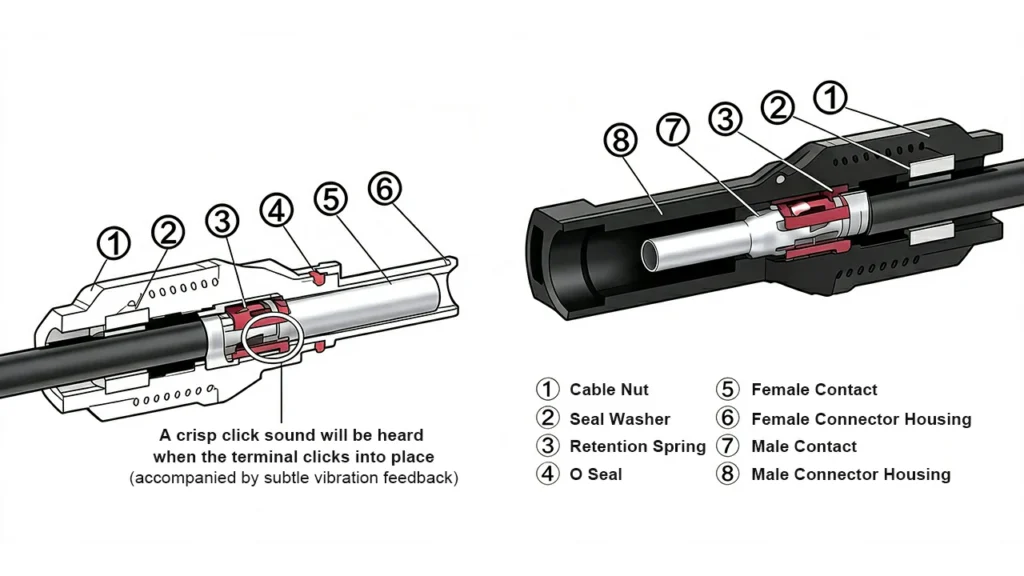
The first thing to understand about MC4 connector compatibility is that the MC4 form factor — the external dimensions that allow two connectors to physically mate — is not a standard. It is a de facto quasi-standard that emerged when Stäubli’s original MC4 patents expired and dozens of manufacturers began producing connectors with the same external geometry.
When a manufacturer says their connector is “MC4 compatible,” they mean it shares the MC4 form factor. They do not mean — and cannot mean — that it has been certified to mate safely with every other manufacturer’s MC4-form connector. The distinction is between geometry and engineering.
Here is what varies between manufacturers inside the MC4 form factor:
Contact pin diameter tolerance. The male pin is nominally 4mm in diameter, but manufacturers optimise within the permitted tolerance range. A pin at the upper end of tolerance combined with a spring contact at the lower end of tolerance produces higher insertion force and may not seat fully. A pin at the lower end combined with a loose spring contact produces reduced contact area — and higher contact resistance.
Spring contact geometry and force. The female spring contact must grip the male pin firmly enough to maintain gas-tight electrical contact through 25 years of thermal cycling, vibration, and UV exposure. Spring force, finger count, and contact geometry are each manufacturer’s proprietary design — they are not standardised beyond the IEC 62852 performance test, which tests each connector against its own paired half.
Housing outer diameter and face seal geometry. The IP67 face seal between mated connector halves depends on the mating surfaces of both housings. If Manufacturer A’s male housing has a different outer diameter or seal land geometry from Manufacturer B’s female housing, the face seal is compromised. The connection may pass a visual inspection and fail a 24-hour water immersion test — but nobody on a rooftop is running that test.
Locking tab geometry. The locking tabs that produce the audible click when two MC4 connectors mate are not standardised. Tab depth, engagement notch geometry, and spring force vary between manufacturers. A cross-brand connection may click — indicating partial engagement — without achieving the full locking depth that prevents pull-out under cable load. The pull-out force of a fully locked same-brand connection is defined and tested; a cross-brand connection’s pull-out force is unknown.
None of these differences are visible to the installer. Every cross-brand combination that physically mates looks identical to a correctly mated same-brand connection.
What the Standards Actually Say
MC4 connector compatibility is not a grey area in the applicable standards. The requirements are explicit.
IEC 60364-7-712:2017, the installation standard for solar PV systems, states directly: “male and female connectors shall be of the same type from the same manufacturer.” This is a mandatory requirement in the installation standard, not a recommendation. An installation that uses cross-brand MC4 connections does not comply with IEC 60364-7-712 regardless of whether the individual connectors are each separately certified.
IEC 62852, the product standard for DC connectors in PV systems, governs the testing and certification of individual connectors. IEC 62852 includes an intermateability assessment process, but this requires both manufacturers to participate and share design information — it does not create automatic cross-compatibility between all certified products. Certification under IEC 62852 applies to a connector mated with its own paired half.
UL 6703, the North American standard for PV connectors, takes an identical position: UL certification for a connector pair applies only when connectors from the same product family are mated. Neither UL, CSA nor TÜV will certify the cross-mating of PV connectors unless there is a contractual agreement between the two companies to share the certification and all pertinent construction information.
NEC 2020 and later editions have moved toward codifying the same-manufacturer requirement for US installations, with AHJs in many jurisdictions now actively enforcing connector brand consistency during inspection.
The legal consequence is straightforward: cross-mating voids the warranty of both the connector manufacturer and typically the panel manufacturer. In the event of a fire or system failure traced to a cross-brand connection, neither manufacturer carries liability — and the installer or system owner does.
How TÜV Rheinland Quantifies the Risk: The RPN Framework
The most rigorous quantification of cross-brand MC4 connector compatibility risk comes from TÜV Rheinland’s failure mode analysis, which uses a Risk Priority Number (RPN) framework standard in engineering failure mode analysis.
The RPN is calculated as: RPN = Severity × Occurrence × Detectability
Each factor is rated on a scale where higher numbers indicate worse outcomes:
- Severity: How serious is the failure when it occurs? For cross-brand MC4 connections, the severity rating reflects the potential for arc fault initiation, fire, and complete system loss — the highest severity tier.
- Occurrence: How likely is the failure to occur? Cross-brand mating is a documented, recurring failure mode with known physical mechanisms. Occurrence is rated as frequent given the prevalence of mixed-brand installations.
- Detectability: How easily can the failure be detected before it causes harm? This is where cross-brand MC4 mating scores worst. The failure is invisible on installation. It produces no immediate indication at commissioning. It develops over months to years of thermal cycling before manifesting as a detectable thermal anomaly — and by that point, significant degradation has already occurred.
Studies conducted by SolarBankability, TÜV Rheinland, a group of international scientists, and the IEA PVPS report on “Quantification of Technical Risks in PV Power” unequivocally state that cross-mating different connector brands significantly increases the technical and legal risk of a PV system. TÜV Rheinland’s failure mode analysis identifies cross-mated PV connectors as the single greatest risk to PV system performance and safety — not a significant risk among many, but the top-ranked risk in their analysis.
The reason detectability scores so poorly is the sealed nature of the MC4 connector itself. The IP67 housing that protects the connection from weather also traps the heat generated by an elevated-resistance cross-brand contact. The heat cannot dissipate; it accumulates inside the sealed housing, driving progressive degradation that is invisible externally until the housing begins to deform or discolour — by which point the internal damage is already severe.
The Failure Mechanism: From Contact Resistance to Arc Fault
Understanding the physical progression from a cross-brand connection to a system fire explains why the risk is real and not theoretical.
Stage 1 — Elevated contact resistance at installation. A cross-brand MC4 connection with mismatched pin tolerance and spring geometry achieves a contact area smaller than the designed same-brand pair. Contact resistance is measurably higher — perhaps 2–5× the same-brand value of ≤0.5 mΩ. At installation, this produces slightly more heat than a correctly mated connection, but not enough to be immediately detectable.
Stage 2 — Thermal cycling initiates progressive loosening. Every day, the operating current through the connection produces I²R heating that expands the metal contacts and housing. Every night, cooling contracts them. Across thousands of thermal cycles over years of operation, this mechanical cycling works the contact slightly loose — increasing the air gap between pin and spring, reducing contact area further, and increasing resistance. The process is self-accelerating: more resistance produces more heat, which produces more thermal cycling stress, which loosens the contact further.
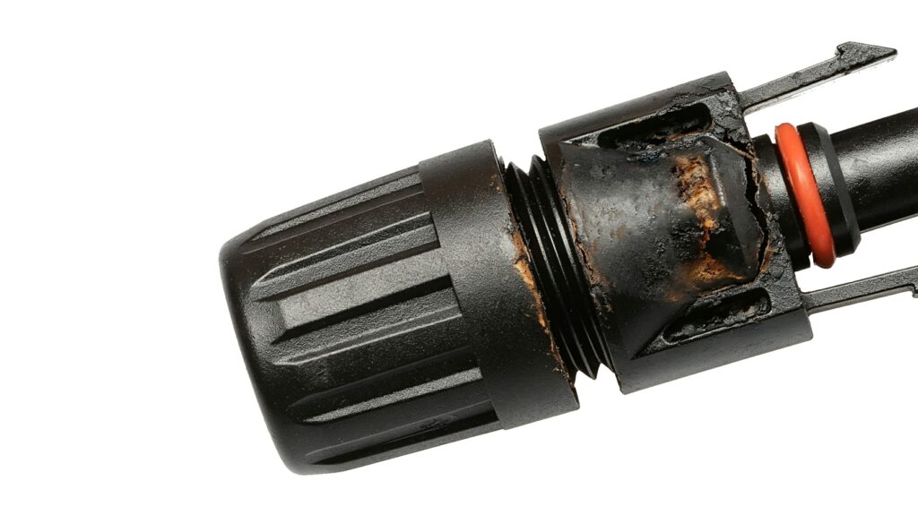
Stage 3 — Moisture ingress accelerates corrosion. A cross-brand connection with a mismatched face seal geometry allows moisture to reach the contact interface. Copper contacts oxidise in the presence of moisture, forming copper oxide — a semiconductor with orders of magnitude higher resistance than clean copper. Oxide formation is irreversible and accelerates contact degradation.
Stage 4 — Arc initiation. As contact resistance reaches a threshold where the voltage across the contact interface exceeds the ionisation threshold of the gap, a series arc initiates. The arc is sustained by the DC string voltage — there is no natural zero crossing to extinguish it. The arc burns at temperatures exceeding 5,000°C, carbonising the plastic housing from inside.
Stage 5 — Fire. The carbonised housing eventually allows the arc to reach the outer housing surface or adjacent materials. The UL94-V0 flame class of the housing material means it resists self-ignition, but sustained arc energy at these temperatures exceeds the material’s thermal resistance.
This progression typically occurs over one to five years from installation — long enough that the cross-brand mating is not immediately identified as the cause, and long enough that the installer may no longer be traceable.
What “MC4 Compatible” on a Module Datasheet Actually Means
This is the question that causes the most confusion on job sites, and it deserves a direct answer.
When a module manufacturer’s datasheet says “MC4 compatible connector” or “MC4 type connector,” it means the module’s pre-installed connector leads use a connector with the MC4 form factor. It does not mean those connectors are made by Stäubli. It does not mean they have been certified for cross-brand mating with any specific third-party connector. It means the connector will physically mate with other MC4-form connectors.
Module datasheets say “MC4 compatible” all the time, even when you see a different manufacturer’s connector on the cables when the material shows up. The actual connector brand installed at the module junction box may be any of dozens of manufacturers — Stäubli, QC Solar, Renhe, PNTECH, Amphenol, or any number of others depending on the panel manufacturer’s procurement decisions at the time of production.
The correct installer response when a module datasheet says “MC4 compatible”:
- Physically inspect the connector installed on the module leads — look for the manufacturer’s name or logo moulded into the housing. Common locations are the flat face of the connector or the side of the cable entry section.
- If the manufacturer name is not visible, contact the module supplier and request the connector brand and part number for that specific production batch. Module manufacturers change connector suppliers between production runs.
- Once the connector brand on the module is identified, use the same brand for all extension cables, combiner box inputs, and string-level connections in that string.
- Document the connector brand used in each string in the system commissioning records — this information is essential for future maintenance and expansion work.
The principle is simple: the connector brand on the module lead determines the connector brand for the entire string. The installation contractor’s preferred connector brand is irrelevant if it differs from what is on the module.
The “Compatible” Testing Trap: Why Third-Party Test Reports Are Not Certification
A significant source of confusion in the MC4 connector compatibility debate is the existence of third-party test reports that state specific cross-brand connector pairs “passed” intermateability testing. These reports are real, they are produced by accredited laboratories, and they are not certification of cross-brand compatibility.
The distinction is between a Design Type Certificate and an Individual Test Report.
A Design Type Certificate under IEC 62852 or UL 6703 means a connector product has been tested as a system — the male and female halves of the same product family tested together — and the complete product has been certified to meet the standard’s performance requirements. This certification applies to the product as sold.
An Individual Test Report means a laboratory has taken two specific connector samples from two different manufacturers, mated them, and tested the mated pair against some subset of performance criteria. The test report describes the result of that specific test. It does not mean the connector pair is certified for cross-brand mating in service. It does not cover the full range of tolerance combinations that will be encountered across a production run of millions of connectors. And it carries no warranty or liability coverage from either manufacturer.
Stäubli dissociates itself from cross-connecting components of 3rd party suppliers, being advertised as “MC4 compatible.” They further disclaim any participation in tests from independent test institutes that are misleading and wrongly indicate compatibility. When a third-party manufacturer’s marketing materials cite a TÜV or UL “test report” confirming compatibility with MC4, that report describes a single test — it does not constitute certification of the cross-brand combination.
The practical consequence: an installer who uses cross-brand MC4 connections on the basis of a third-party test report remains in a non-compliant installation under IEC 60364-7-712, and neither manufacturer’s warranty or liability coverage applies to that connection.
Identifying Cross-Brand Mating in Existing Systems
For operations and maintenance teams working with existing installations, MC4 connector compatibility assessment is a standard part of the annual inspection. The process has four stages.
Stage 1 — Visual Brand Identification
Visually distinguishing MC4 connector brands in the field is not straightforward — most manufacturers, including many premium producers, do not mould brand names into the connector housing. Identification relies on a combination of approaches:
Check the original packaging and delivery documentation. Connector reels, bags, and cartons carry the manufacturer’s name and part number. If the project’s installation records include material delivery documentation, the connector brand should be traceable from there.
Check the cable assembly label. Where extension cables or pre-assembled pigtails are used, the manufacturer’s name often appears on the cable assembly label rather than the connector housing itself.
Contact the module supplier. For connectors pre-installed on module leads, the only reliable identification method is to contact the module supplier or manufacturer with the panel model number and production batch date code. Request written confirmation of the connector brand and part number for that specific batch — module manufacturers sometimes change connector suppliers between production runs, so batch-specific confirmation is essential.
Compare housing geometry. Experienced installers can often distinguish connector brands by subtle differences in housing profile, cable gland shape, and locking tab geometry — but this requires hands-on familiarity with multiple brands and is not a reliable method for unfamiliar products.
Where connector brand cannot be confirmed through documentation, treat all connections involving that string as unverified and schedule contact resistance measurement and thermal imaging as a priority.
Stage 2 — Thermal Imaging Under Load
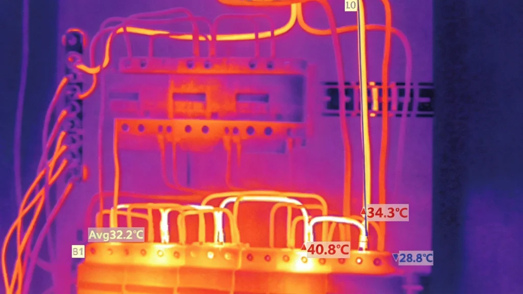
Perform infrared inspection of all accessible MC4 connections under full-sun conditions with the system at 80% or more of rated power. A same-brand, correctly installed connection will show a temperature within 3–5°C of adjacent connections on the same string. A cross-brand connection with elevated contact resistance will show measurably higher temperature — potentially 10–30°C above adjacent connections depending on the degree of mismatch and the stage of degradation.
Any connection showing more than 10°C above adjacent connections on the same string requires pull-test verification and likely replacement regardless of visible brand markings.
Stage 3 — Pull Testing
For connections identified as cross-brand or showing thermal anomalies, perform a pull test per IEC 62852 — apply 50N of pull force axially to the mated pair. A correctly locked same-brand connection will not separate. A cross-brand connection with incompatible locking geometry may separate under pull test load, confirming inadequate locking engagement.
Stage 4 — Contact Resistance Measurement
Where pull tests are passed but thermal anomalies persist, use a milliohmmeter or low-resistance ohmmeter to measure contact resistance across the mated pair at the connector (excluding cable contribution). A correctly mated same-brand connection with an uncorroded contact should read ≤1 mΩ including short cable leads. Readings above 5 mΩ confirm elevated contact resistance that warrants replacement.
Remediation: Standardising a Mixed-Brand System
When cross-brand MC4 mating is identified in an existing system, the correct response is to standardise to a single connector brand throughout the affected string. The process:
Step 1 — Identify the connector brand on the module leads. This is the reference brand for the string. The module connector cannot be changed without accessing the junction box and potentially voiding the module warranty.
Step 2 — Replace all non-matching connectors on extension cables and combiner box inputs. Cut the existing non-matching connector from the cable, re-terminate with a connector from the same brand as the module lead, following the installation procedure in our How to Install MC4 Connectors guide.
Step 3 — Replace both halves of any connection where arc damage or discolouration is present. Do not re-mate an arced connector with a new half — carbon deposits on the contact surface of the undamaged half will immediately contaminate the new contact. Both halves must be replaced, and the cable section adjacent to a severely arced connector should be inspected for insulation damage and replaced if affected.
Step 4 — Perform post-remediation testing. After standardisation, perform contact resistance measurement on all replaced connections (target ≤1 mΩ), pull testing (minimum 50N), and insulation resistance testing of the affected strings before re-energising.
Step 5 — Update documentation. Record the connector brand used in each string in the system’s O&M documentation. This prevents future maintenance crews from inadvertently introducing cross-brand connections during repair or expansion work.
Procurement Strategy: Preventing Cross-Brand Mating Before It Happens
The most effective MC4 connector compatibility management happens in procurement, before materials reach the job site. A mixed-brand connection cannot happen if only one brand of connector is in the project BOM.
At the design stage: Specify the connector brand based on the confirmed connector type on the module leads — obtain this from the module supplier for the specific production batch, not from the datasheet alone. Make the connector brand an explicit specification in the project BOM.
At procurement: Source all field-installed connectors — extension cables, combiner box pigtails, and T/Y branch connectors — from the same manufacturer as the module lead connectors. Moreday’s MC4 Connector range is available in both 1000V and 1500V variants with consistent geometry across the full T-branch and Y-branch family, simplifying single-brand procurement for complete string protection.
At delivery: Inspect incoming connector materials to verify brand consistency before they reach the installation crew. A project that receives mixed-brand connectors due to a supply chain substitution should resolve the discrepancy before installation, not after.
At installation: Brief installation crews on the same-brand requirement and the rationale. An installer who understands why cross-brand mating is dangerous is more likely to flag a discrepancy than one who has only been told “use these connectors.”
At commissioning: Include connector brand verification in the commissioning checklist — confirm that male and female connector halves in each string carry consistent manufacturer markings before the system is energised.
This five-stage procurement discipline adds negligible time and cost to a project. The alternative — identifying and remediating cross-brand connections in an installed system — is significantly more expensive and carries ongoing fire risk until remediation is complete.
FAQ
For guidance on correct MC4 connector installation to prevent the workmanship errors that compound cross-brand compatibility risks, see our How to Install MC4 Connectors guide. For understanding the arc fault consequences of connector failures, see DC Arc Faults in Solar Systems. For the complete overview of MC4 connector types and specifications, see our MC4 Connector Complete Guide.
External references: IEC 60364-7-712:2017 — Requirements for special installations: Solar photovoltaic power supply systems (iec.ch); IEC 62852 — Connectors for DC-application in photovoltaic systems (iec.ch); UL 6703 — Connectors for Use in Photovoltaic Systems (ul.com)