
Solar
The MC4 connector is the universal interface of the solar industry — the small, black, click-together fitting that links every PV module to the cables, combiner boxes, and inverters that carry its output to the grid. Virtually every solar panel shipped today arrives with MC4 connector leads pre-attached at the junction box. Yet despite this ubiquity, MC4 connectors are responsible for approximately 40% of urgent safety issues identified in PV system inspections — not because the design is flawed, but because they are routinely misused, mismatched, and under-specified.
This guide covers everything a buyer, installer, or engineer needs to know about MC4 connectors: how they work, what the types and variants mean, how to specify them correctly for 1000V and 1500V systems, why cross-brand mating is dangerous, how to install them correctly, and how to identify the difference between a certified product and a counterfeit.
What Is an MC4 Connector?
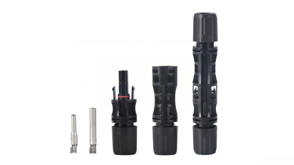
The name “MC4” derives from its origin: Multi-Contact (the Swiss connector company, now Stäubli Electrical Connectors) and the 4mm diameter of the internal contact pin. Introduced in the early 2000s to replace the earlier MC3 design, the MC4 connector quickly became the global standard for DC wiring in photovoltaic systems.
The international standard governing MC4 connectors and their MC4-compatible equivalents is IEC 62852 — DC connectors for photovoltaic systems. This standard defines requirements for contact resistance, pull-out force, weather sealing, UV resistance, flame class, and intermateability testing. Any MC4 connector sold into professional PV markets should reference compliance with IEC 62852.
As of 2024, the global MC4 connector market was valued at approximately $3.7 billion, with a projected compound annual growth rate of 12% through 2030 — driven by the continued expansion of solar capacity worldwide and the transition to higher-power module formats that require higher-rated connectors.
How an MC4 Connector Works: Internal Structure
Understanding the MC4 connector’s internal structure explains both its strengths and the failure modes that arise when it is incorrectly specified or installed.
The Contact System
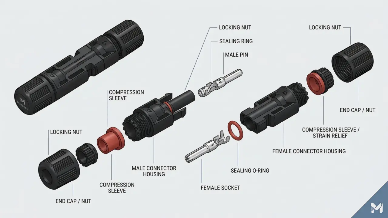
Each MC4 connector half — male (plug) and female (socket) — contains a metal contact element inside a plastic housing. The male contact is a solid 4mm copper-alloy pin; the female contact is a spring-loaded sleeve that grips the pin under insertion force. Both contacts are made from tin-plated or silver-plated copper alloy, selected for low contact resistance (specified at ≤0.5 mΩ in Moreday’s product range), good spring retention over thermal cycling, and resistance to galvanic corrosion.
When the male and female halves are pushed together, the pin seats fully into the spring sleeve, creating a gas-tight connection with contact resistance in the sub-milliohm range. This low contact resistance is the critical performance parameter — a correctly assembled MC4 connection at 10A generates less than 0.05 mW of heat. A poorly crimped or partially mated connection with 10× the contact resistance generates proportionally more heat and begins the progressive failure cycle that leads to arc fault initiation.
The Locking Mechanism
The outer plastic housing includes a snap-lock mechanism that secures the mated pair against accidental separation. On the standard MC4 design, two locking tabs on the female housing engage notches on the male housing when pushed together. Separation requires an MC4 disconnect tool — a spanner-style key that simultaneously depresses both locking tabs while the connector halves are pulled apart.
This locking mechanism serves two purposes: it prevents wind, vibration, or cable weight from pulling connectors apart on rooftop installations, and it provides a visible indication of correct mating — a properly seated connection clicks audibly and resists pull-out. A connector that does not click or that can be pulled apart by hand without the disconnect tool is not correctly mated.
The IP67 Seal
The MC4 connector’s IP67 weatherproofing rating — complete dust protection and temporary water immersion to 1 metre — is achieved through two sealing elements. A compression gland at the cable entry seals around the cable jacket when the cable nut is tightened. A face seal between the mated connector halves prevents moisture ingress at the connection interface.
Both seals depend on correct cable diameter. The compression gland is designed for a specific cable diameter range — typically 5–7mm outer diameter for 4mm² cable, or 6–8.5mm for 6mm² cable. Using a cable outside the specified diameter range leaves the gland partially open and compromises the IP67 rating. This is a common cause of moisture-related connector failure in the field, particularly when generic cable is used with branded connectors or vice versa.
MC4 Connector Types: The Complete Moreday Range
Not all MC4 connectors are the same device. The term “MC4 connector” covers a family of related products serving different functions in PV system wiring. Understanding this family is essential for correct specification.
Standard Pair Connectors (1000V and 1500V)
The fundamental MC4 connector pair — one male and one female — for series-connected string wiring. Standard pairs connect module-to-module within a string and module leads to extension cables.
1000V MC4 Connector: Rated for systems up to 1000V DC, 30A continuous current, IP67, ≤0.5 mΩ contact resistance, cable sizes 4–6mm². The standard choice for residential rooftop PV and small commercial installations where string voltage does not exceed 1000V.
1500V MC4 Connector: Rated for systems up to 1500V DC, 30A or 45A depending on variant, IP67, cable sizes 4–6mm² (30A) or 10mm² (45A). Required for large commercial and utility-scale installations using 1500V DC architecture. The 1500V connector uses increased creepage and clearance distances within the housing to prevent tracking at higher voltage — it is not simply a rebranded 1000V device, and the two should not be mixed in the same string.
PV-MD-MC4-S: A dual-rated variant accepting both 1000V and 1500V systems with a 10mm² cable size — designed for high-current applications such as combiner box output connections and battery storage DC interfaces where larger conductor cross-sections are required.
Function MC4 Connectors
These MC4-form connectors integrate protective components into the connector body, reducing the need for separate protective devices in the DC string circuit.
MC4 Connector with Fuse: Integrates a DC fuse within the connector housing, providing string-level overcurrent protection at the panel output. Available in 20A and 30A ratings, 1000V and 1500V variants, cable sizes 2.5–6mm². Particularly useful in parallel-connected systems where individual string fuse protection is required per IEC 60364-7-712 or NEC 690.9 but where a dedicated combiner box is not practical. The integrated fuse approach reduces the external component count and eliminates a separate fuse holder connection point — one of the locations where contact resistance problems develop over time.
MC4 Connector with Diode: Integrates a bypass diode within the connector housing. Rated at 1000V, available in 10A, 15A, and 20–30A variants, cable sizes 2.5–6mm². Used where additional bypass diode protection beyond the module’s internal bypass diodes is desired — for example, in partial shading scenarios or for protecting older modules whose internal diodes have degraded. The diode connector is wired in parallel across the string element it is protecting, providing a current path around a shaded or damaged module section.
T Branch Connectors (T2 through T6 and T4(H)/T5(H))
T branch connectors divide or combine DC circuits at a single connection point, enabling parallel wiring configurations without a combiner box. The numerical suffix indicates the number of cables connected at the branch:
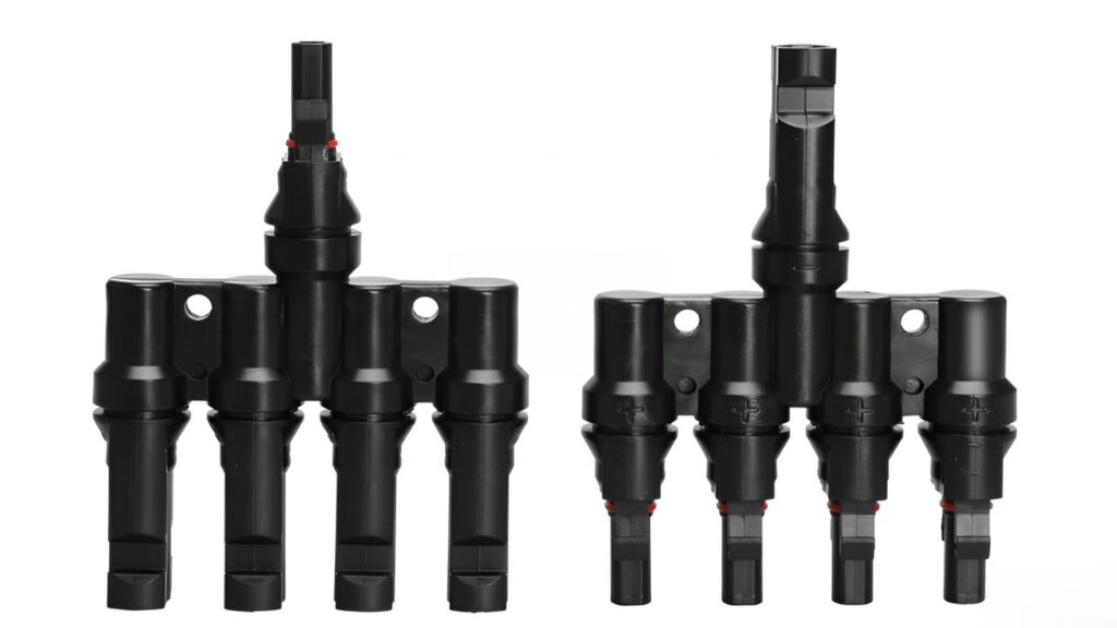
T2 (2-into-1 or 1-into-2): Connects two parallel inputs to one output. The standard two-string parallel connection, used where two strings are combined before routing to the inverter or string-level combiner input.
T3 (3-into-1): Three parallel inputs combined to one output. Used for three-string parallel combinations — note that at three parallel strings, IEC 60364-7-712 and NEC 690.9 require individual string overcurrent protection due to reverse current risk, making the MC4 connector with fuse variant particularly relevant at this configuration.
T4, T5, T6: Four, five, and six input branches respectively. For larger parallel combinations on utility or large commercial installations. At these configurations, current ratings must be carefully verified — the output conductor of a T6 connector carries the sum of six string currents and must be sized accordingly.
T4(H) and T5(H): High-current variants of the T4 and T5 configurations with reinforced contact systems rated for higher continuous current. Specified where string currents from high-output modules push total combined current near the standard variant’s limit.
Y Branch Connectors (Y2 through Y4)
Y branch connectors perform the same parallel combination function as T branch connectors but with a different physical form factor — a Y-shaped body rather than the T-shape. The Y configuration is preferred in installations where cable routing requires a specific orientation, or where the physical layout of the array makes the Y geometry more practical than T.
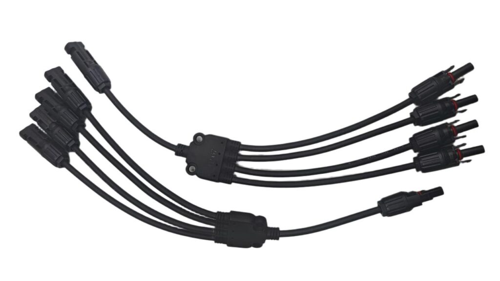
Y2: Two inputs to one output — equivalent in function to T2, different in form.
Y3: Three inputs to one output.
Y4: Four inputs to one output.
The selection between T and Y variants for a given application is primarily a routing and installation preference — the electrical ratings and performance specifications are equivalent between the T and Y families at the same branch count.
MC4 vs Other Solar Connector Types
The solar connector market contains several connector types beyond MC4. Understanding where MC4 sits relative to these alternatives is important for system design and for handling existing installations that may use non-MC4 connectors.
MC3 (Legacy)
The predecessor to MC4, MC3 connectors use a 3mm contact pin and lack the secure locking mechanism introduced in the MC4 design. MC3 connectors are found on solar panels installed more than 10–15 years ago. They are no longer specified for new installations — most electrical codes require a locking connector design for PV DC applications — but they appear in retrofit and upgrade projects.
MC3 to MC4 adapters exist but are not recommended for permanent installations. The preferred approach when upgrading an MC3 system is to replace the connector leads at the junction box with MC4-terminated cables.
T4 Connectors
T4 connectors were developed by Tlian, a subsidiary of Canadian Solar, as an alternative to MC4 with certain design refinements. T4 connectors have a different locking geometry and contact design from MC4, and they are not cross-compatible with MC4 connectors without an adapter. Canadian Solar panels commonly ship with T4 connectors pre-installed; where a T4-equipped system is being extended or modified, T4 connectors should be used throughout, or the connector type should be standardised to MC4 using certified adapters or replacement leads.
Moreday’s T2–T6 branch connectors are MC4-design branch connectors — these designations refer to the branch count, not to the T4 connector format. The two naming conventions are unfortunately similar and a source of specification confusion.
H4 Connectors (Amphenol)
Amphenol’s H4 connector is a high-quality MC4-compatible design used by several module manufacturers. H4 connectors mate with MC4-design connectors from certified compatible manufacturers but should not be cross-mated with uncertified MC4-compatible products.
TE SOLARLOK and Radox
TE Connectivity’s SOLARLOK and Stäubli’s Radox connectors are specialised designs used in specific module ranges and not generally compatible with MC4. They appear primarily in industrial and utility-scale installations using specific module brands. If encountered during maintenance or expansion work, the connector type must be identified and matched — cross-mating with MC4 is not appropriate.
The MC4 Compatibility Problem: Why Cross-Brand Mating Is Dangerous
This is the MC4 topic that generates the most field problems and the most forum debate — and it deserves a clear, definitive explanation.
Why Brands Can Appear Compatible But Aren’t
When Stäubli’s original MC4 patent expired, dozens of manufacturers began producing MC4-compatible connectors. The IEC 62852 standard governs the technical requirements, and many of these products are certified against it. However, IEC 62852 certification of a connector’s individual performance does not guarantee intermateability — the ability to safely mate connectors from different manufacturers.
The reason is subtle but important. The male pin diameter, female spring contact geometry, locking tab depth, housing outer diameter, and compression gland design all interact when two connectors are mated. Manufacturers optimise these dimensions within the IEC 62852 tolerance bands to suit their specific contact and housing geometry. When a male connector from Manufacturer A is mated with a female connector from Manufacturer B, the dimensional interaction may produce:
- Higher contact resistance than either connector achieves with its own pair: The spring contact of B may not fully grip the pin of A, leaving a smaller contact area and higher resistance. Even 5–10× the normal contact resistance, while undetectable by visual inspection, causes measurable heating under load.
- Incomplete locking: The locking tabs of B may not fully engage the notches of A, creating a connection that appears locked but can separate under vibration or cable pull.
- Compromised IP sealing: The face seal geometry depends on the mating surfaces of both halves. A mismatch in housing dimensions leaves gaps in the seal, allowing moisture ingress.
None of these problems are necessarily visible when the connectors are first mated. They manifest over time, under thermal cycling and weather exposure, as the connection degrades from borderline to failure.
The Consequence: Arc Fault Initiation
A high-resistance cross-brand MC4 connection is a resistive heat source operating inside an IP67-sealed housing that is also UV- and weather-resistant — meaning the heat has nowhere to go except into the connector body. The temperature rises progressively with each thermal cycle. The plastic housing is rated to UL94-V0 flame class, meaning it resists self-ignition, but prolonged elevated temperature degrades the material and eventually carbonises the contact surfaces. Carbon deposits further increase resistance, accelerating the temperature rise. The end state is a sustained arc fault at the connector — the precise scenario that accounts for 40% of urgent PV safety issues in field inspections.
What IEC 62852 Says About Intermateability
IEC 62852 includes an intermateability assessment process, but it requires the manufacturer to declare which specific connector models from other manufacturers their product is compatible with — it does not create universal cross-compatibility between all certified products. Stäubli explicitly states that MC4 warranty and certification coverage applies only when MC4 connectors are mated to other Stäubli MC4 connectors of the same type.
The Practical Rule
Never mix MC4 connector brands within the same string or connection pair. If a panel arrives with one brand of MC4 pre-installed at the junction box, the extension cables and combiner box connections for that string should use the same brand. Where different brands are already present in an existing system, the safest corrective action is to standardise to a single brand throughout the string, replacing connector leads at the junction box where necessary. Do not use adapters as a permanent solution for cross-brand mating.
MC4 Connector Specifications: What to Check When Buying
The nameplate and datasheet of any MC4 connector should confirm the following parameters before purchase. For professional PV applications, a supplier who cannot provide documentation for all of these parameters is not an appropriate source.
| Parameter | What to check | Moreday standard |
|---|---|---|
| Rated voltage | 1000V DC or 1500V DC — must match or exceed system voltage | 1000V / 1500V variants available |
| Rated current | Must exceed maximum string current at worst-case temperature | 30A (standard) / 45A (1500V high-current) |
| Contact resistance | ≤0.5 mΩ initial — lower is better | ≤0.5 mΩ |
| IP rating | IP67 minimum for outdoor PV applications | IP67 |
| Flame class | UL94-V0 — self-extinguishing material | UL94-V0 |
| Cable size compatibility | Must match the cable cross-section in use | 2.5 / 4 / 6 / 10 mm² variants |
| Operating temperature | −40°C to +105°C or better for outdoor use | −40°C to +105°C |
| Certification | IEC 62852, TÜV, UL 6703 as applicable to market | IEC 62852, TÜV, CE |
| Contact material | Tin-plated or silver-plated copper alloy | Tin-plated copper alloy |
How to Install MC4 Connectors: Step-by-Step
Correct MC4 connector installation is the single most effective prevention measure against connector-related arc faults. The process is straightforward when done correctly — and the most common errors are entirely avoidable.
Tools Required
- Calibrated ratchet crimping tool with the die set specified by the connector manufacturer
- Wire stripper calibrated to the conductor cross-section
- MC4 disconnect tool (spanner key) — for testing and future maintenance
- Torque screwdriver if the cable nut has a specified tightening torque
- Pull-out test gauge (recommended for commercial installations)
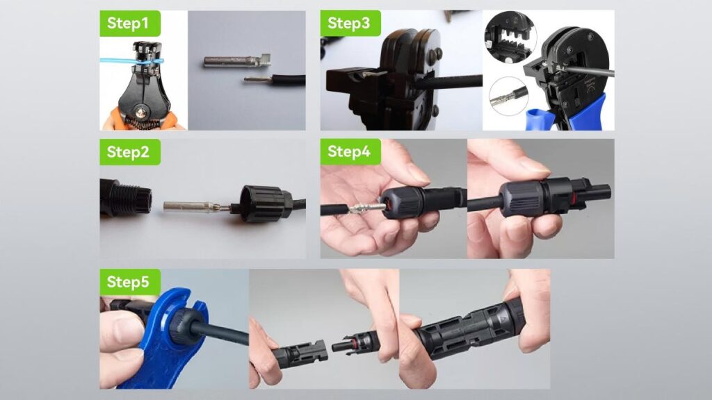
Step 1 — Strip the cable
Strip the cable insulation to the length specified by the connector manufacturer — typically 10–12mm for Moreday MC4 connectors. Use a calibrated wire stripper set to the exact conductor cross-section to avoid nicking strands. A nicked conductor at the crimp point concentrates stress and creates a high-resistance zone that worsens over time.
Do not over-strip. Exposed conductor beyond the contact crimp barrel can contact the housing interior or compromise the cable gland seal. Under-stripping leaves insufficient conductor in the crimp zone, reducing the crimped contact area and increasing contact resistance.
Step 2 — Insert and crimp the contact
Insert the stripped conductor fully into the metal contact barrel — the conductor ends should be visible at or slightly beyond the far end of the crimp barrel. Use the ratchet crimping tool with the die size specified for the conductor cross-section and contact type. The ratchet mechanism ensures the crimp completes fully before releasing — do not attempt to open the tool before the ratchet releases.
A correctly crimped contact is gas-tight: the compression has eliminated air gaps between the conductor strands and the contact barrel, preventing oxidation at the interface. A gas-tight crimp maintains stable contact resistance over the connector’s 25-year service life. An incomplete crimp begins to oxidise at the contact interface within months, progressively increasing resistance and initiating the failure sequence described above.
Step 3 — Assemble the housing
Thread the cable nut and cable gland onto the cable before inserting the crimped contact into the housing — these cannot be added after the contact is seated. Insert the crimped contact into the housing from the cable entry end, pushing until it clicks into the retention feature in the housing body. A correctly seated contact cannot be pulled back out by hand.
Tighten the cable nut to the torque specified in the manufacturer’s installation guide — typically 2–3 Nm for standard MC4 cable nuts. The cable nut compresses the gland around the cable jacket to achieve the IP67 cable entry seal.
Step 4 — Mate the connectors
Push the male and female halves together with firm, even pressure until the locking tabs click audibly into the engaged position. Verify by attempting to separate the connectors by hand — a correctly locked pair requires the MC4 disconnect tool to separate.
Perform a pull test on a sample of connections: apply the pull force specified in IEC 62852 (minimum 50N) and verify that the connection does not separate. For commercial installations, document pull test results as part of the commissioning record.
Step 5 — Verify the connection
Measure contact resistance across the mated pair using a low-resistance ohmmeter or milliohmmeter. A correctly assembled MC4 connection should read ≤1 mΩ including the cable contribution. A reading above 5 mΩ indicates a problem — insufficient crimp, incomplete mating, or cross-brand compatibility issues — that should be resolved before the system is energised.
Common MC4 Connector Installation Mistakes
Using the wrong crimping tool. A standard wire crimper or pliers does not produce a gas-tight crimp in an MC4 contact barrel. The contact dimensions and required compression ratio are specific to the MC4 contact design. Using any crimping tool other than one calibrated for MC4 contacts produces a mechanically adequate but electrically poor connection that will degrade in service.
Mixing connector brands. As detailed above, this is the single most dangerous and most common MC4 installation error. The consequences are elevated contact resistance, compromised sealing, and progressive arc fault risk. Use one brand throughout each string.
Over-stripping the cable. Exposed conductor inside the housing can contact the outer shell or compromise the gland seal. Strip to the exact length specified.
Not completing the crimp. A ratchet tool that is forced open before completing the cycle produces an incomplete crimp. The tool must be allowed to complete the ratchet cycle fully before reopening.
Ignoring the cable gland torque specification. Hand-tight is not tight enough. The cable nut must be torqued to specification to compress the gland and achieve IP67 sealing. Undertorqued cable nuts allow moisture ingress that corrodes the contact over time.
Skipping the pull test. A pull test takes five seconds per connector and provides definitive confirmation of correct locking. Skipping it and discovering an unlocked connection during the first high-wind event is a significantly more expensive outcome.
MC4 Connector Maintenance and Replacement
MC4 connectors are designed for a 25-year service life when correctly installed with matched brands and cable sizes. However, they require periodic inspection and have defined replacement criteria.
Annual Thermal Imaging
Infrared inspection of the complete DC circuit — including every accessible MC4 connector — should be performed annually on commercial systems and biennially on residential systems. Perform inspection under full-sun conditions with the system at 80% or more of rated power.
A healthy MC4 connection will show a temperature within 3–5°C of adjacent connectors on the same string. A connection running 10–20°C above adjacent connectors has elevated contact resistance and is a pre-failure condition that requires repair or replacement before the next inspection cycle. A connection running more than 20°C above ambient is an immediate action item — isolate and replace before the system is re-energised.
Visual Inspection Indicators
At each maintenance visit, inspect accessible connectors for: brown or black discolouration of the housing (indicates previous overheating), cracked or deformed cable boots (indicates moisture ingress risk), connectors that can be partially separated by hand without the disconnect tool (indicates loss of locking integrity), and any connector showing visible melting, carbonisation, or arc damage (immediate replacement).
When to Replace
- Any connector showing thermal discolouration or arc damage: replace immediately
- Any connector that fails the pull test at inspection: replace
- Any cross-brand connector pairing discovered during inspection: replace and standardise to a single brand
- Any connector in a system where the original installer’s brand documentation is unavailable and different connector brands are found mixed in the same string: replace all and standardise
- Connectors at or beyond 25 years of service: proactive replacement as part of system life extension
Do not re-mate arced or overheated connectors after replacement of only one half — the mating surface of the undamaged half is likely contaminated with carbon deposits from the arc event. Replace both halves of every damaged connection.
MC4 Connectors and DC Arc Fault Protection
MC4 connector failures are the leading origin point for DC arc faults in solar PV systems. The connection between connector maintenance and arc fault protection is direct — a correctly maintained MC4 connection is a series arc fault prevention measure.
Standard DC circuit breakers cannot detect the series arc faults that originate at deteriorating MC4 connections. As discussed in detail in our DC Arc Faults in Solar Systems guide, series arc faults occur at normal operating current levels and require dedicated AFCI or AFDD detection devices to identify them. The MC4 connector maintenance programme described above is the complementary prevention layer — reducing the probability of arc initiation at connections before a fault occurs.
The complete protection stack for DC arc fault prevention in a solar PV system combines correct MC4 connector selection and installation with AFCI/AFDD detection, DC MCB overcurrent protection for parallel faults, and SPD protection against transient overvoltages that stress connector insulation. Moreday’s DC MCB range, SPD range, and PV Combiner Box solutions form the overcurrent and surge protection layers of this stack, working alongside correctly specified and maintained MC4 connectors.
Choosing the Right Moreday MC4 Connector for Your Application
| Application | Recommended connector | Key specification |
|---|---|---|
| Residential rooftop PV, ≤1000V system | 1000V MC4 standard pair | 4–6mm², 30A, IP67 |
| Commercial / utility PV, 1500V system | 1500V MC4 standard pair | 4–6mm² (30A) or 10mm² (45A) |
| High-current combiner output | PV-MD-MC4-S | 10mm², 1000V/1500V dual-rated |
| 2-string parallel, no combiner box | MC4 T2 or Y2 branch connector | Match to string current × 2 |
| 3-string parallel with overcurrent protection | MC4 with Fuse + T3 or Y3 | 20A or 30A fuse rating per string |
| Partial shading protection | MC4 with Diode | Match to string current and voltage |
| Large parallel arrays (4–6 strings) | T4/T5/T6 or Y4 branch connectors | Verify output cable rating vs combined string current |
For all applications, use Moreday MC4 connectors with Moreday MC4 connectors throughout the string — do not mix with other brands — and use the MC4 Connector Tool for crimping and disconnection to ensure correct installation and safe maintenance.
FAQ
For related reading on DC protection in solar PV systems, see our DC Circuit Breaker: All You Need to Know guide and our DC Arc Faults in Solar Systems article. For installation wiring practices that apply to the DC circuit beyond the MC4 connector, see DC Circuit Breaker Wiring: Polarity and 6 Costly Mistakes.
External references: IEC 62852 — Connectors for DC-application in photovoltaic systems (iec.ch); UL 6703 — Connectors for Use in Photovoltaic Systems (ul.com)