EV Charging
Introduction
A
s electric vehicles (EVs) become more popular, the focus often shifts to the convenience of onboard chargers. But have you ever wondered about offboard chargers and their role in the EV ecosystem? These are the unsung heroes of EV infrastructure, and understanding them can truly enhance your EV experience. So, let’s explore what offboard chargers are all about, how they work, and why they matter.
Offboard chargers, unlike their onboard counterparts, aren’t built into your vehicle. Instead, they exist externally—think of them as the giant charging stations you see at public charging spots or the robust setups installed at home or work. These chargers are pivotal in the EV charging network, serving as the main source for delivering high amounts of power to your vehicle’s battery.
When you plug your EV into an offboard charger, the charger takes on the task of converting electrical power from the grid into a form that your car can use. This usually means converting alternating current (AC) from the grid into direct current (DC) for the battery. Picture it like a power-up station in a video game—except instead of giving your character extra lives, it’s giving your car the energy it needs to drive further.
Composition of Off-board Charger for Electric Vehicles
The off-board charger mainly consists of two parts: the charger body and the charging terminal, as shown in Figure 1 below.
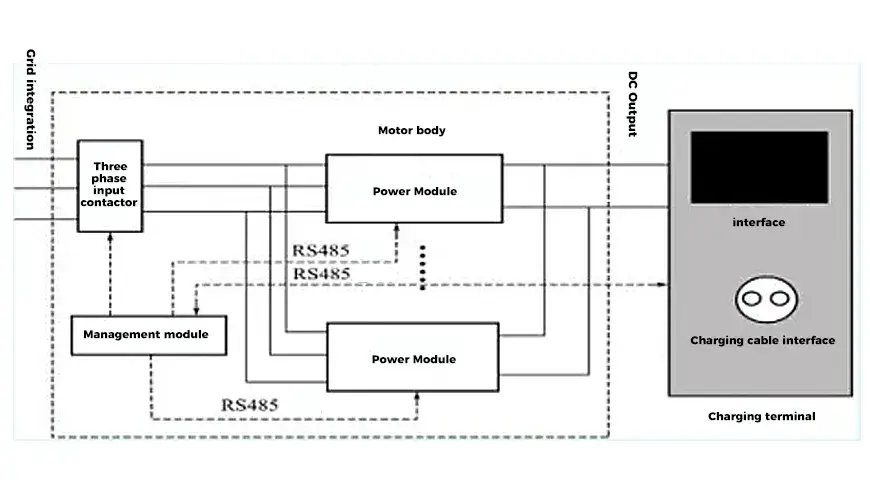
The main body of the charger is connected to the grid through a three-phase input contactor, converting AC power into DC power with adjustable output voltage and current. The output is connected to the battery of the electric vehicle through the charging interface of the charging terminal. The charging terminal faces the user and communicates with the rectifier cabinet control system, battery management system, charging station monitoring system, etc. The charging terminal also has a separate MCU control system to manage the entire terminal. The charging terminal includes an IC card billing system, a printing system, a human-machine panel display system, and an electric energy measurement system, and communicates with the rectifier cabinet control system, battery management system, charging station monitoring system, etc. The relationship between them is shown in Figure 2 below.

The power module is the main body for realizing energy transmission in the non-on-board charger and is the most critical component in the charger. A single power module is difficult to achieve high-power output of the charger, and a distributed system must be selected to achieve it, that is, multiple identical power modules are connected in parallel to share the current.
The human-machine interface should not only provide some information that customers are concerned about during charging, but also provide some necessary information to the maintenance personnel of the charging station, mainly including battery type, charging voltage, charging current, electric energy metering information, the highest/lowest voltage of single battery, fault and alarm information, etc. After charging is completed, the charger needs to print out transaction information, such as power consumption, transaction amount and charging time.
The management module exchanges data with the charging terminal and each power module, and sends the correct charging control command and parameter setting command to each power module through the RS485 bus. As the specific execution module of charging, the power module uploads its own parameters according to the command issued by the management module, or accepts the command of the management module and sets the relevant parameters to complete the charging process. The management module and the power module work together to realize the charging function.
Technical Parameters of Off-board Charger for Electric Vehicles
According to the range of battery pack voltage levels, the output voltage of off-board chargers is generally divided into three levels, namely 150~350V, 300~500V, and 450~700V. The rated output current of off-board chargers should be 10A, 20A, 50A, 100A, 160A, 200A, 315A, 400A, and 500A. When the output power of the off-board charger is 50%~100% of the rated power, the efficiency should not be less than 90% and the power factor should not be less than 0.9.
Non-vehicle charger technical parameter error requirements:
When the AC power supply voltage varies within the range of ±15% of the nominal value and the output DC voltage varies within the specified corresponding adjustment range, the output DC current should remain stable at any value within the range of 20%~100% of the rated value, and the charger output current accuracy should not exceed ±1%; when the AC power supply voltage varies within the range of ±15% of the nominal value and the output DC current varies within the range of 0~100% of the rated value, the output DC voltage should remain stable at any value within the specified corresponding adjustment range, and the charger output voltage accuracy should not exceed ±0.5%.
| Input Method | Input Voltage Rating/V | Input Current Rating/A | Frequency/Hz |
| 1 | Single-phase 220 | In≤10 | 50 |
| 2 | Single-phase 220/Three-phase 380 | 16<In≤32 | 50 |
| 3 | Three-phase 380 | In>32 | 50 |
Electric Vehicle Off-board Charger Input Technical Parameters
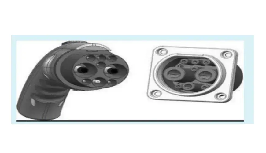
Charging interface of off-board charger for electric vehicles: Contact arrangement of plug and socket of off-board charger for electric vehicles/power supply plug and charging socket of off-board charger for electric vehicles are shown in Figures 1 and 2 below.
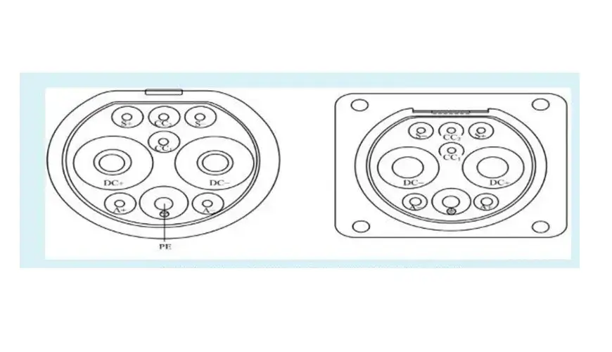
The order of contact coupling between the vehicle plug and the vehicle socket during the connection process is: protective grounding, DC power supply positive, DC power supply negative, vehicle end connection confirmation, low voltage auxiliary power supply positive and low voltage auxiliary power supply negative, charging communication and power supply end connection confirmation; the order is reversed during the disconnection process. The connection interface of the DC charging interface of the off-board charger.
Charging process of off-board charger for electric vehicle: The basic structure of DC charging safety protection system of off-board charger is shown in Figure 1, including off-board charger control device, resistors R1, R2, R3, R4, R5, switch S, DC power supply circuit contactors K1 and K2 (only one can be set), low-voltage auxiliary power supply circuit contactors K3 and K4 (only K3 can be set), charging circuit contactors K5 and K6 (only one can be set), electronic lock and vehicle control device, where the vehicle control device can be integrated into the battery management system. Resistors R2 and R3 are installed on the vehicle plug, and capacitor R4 is installed on the vehicle socket. Switch S is the internal normally closed switch of the vehicle plug. When the vehicle plug and the vehicle socket are fully connected, switch S is closed. During the entire charging process, the off-board charger control device should be able to monitor the contactors K1.K2, contactors K3, K4, and the electronic lock status, and control them to be turned on and off: The vehicle control device of electric vehicles should be able to monitor the contactors K5 and K6 status and control them to be turned on and off.
The Process of Charging Electric Vehicles with an Off-board Charger
After the vehicle plug and socket are plugged in, the overall design of the vehicle can automatically activate a certain trigger condition, making the vehicle in an undriveable state through interlocking or other control measures.
After the operator sets up the charging for the off-board charger, the off-board charger control device determines whether the vehicle plug and the vehicle socket are fully connected by measuring the voltage value of detection point 1. If the voltage value of detection point 1 is 4V, it is determined that the vehicle interface is fully connected, and the off-board charger controls the electronic lock to lock.
After the vehicle interface is fully connected, if the off-board charger completes self-test, contactors K3 and K4 are closed to conduct the low-voltage auxiliary power supply circuit, and the “charger identification message” is periodically sent. After obtaining the low-voltage auxiliary power supply provided by the off-board charger, the vehicle control device determines whether the vehicle interface is fully connected by measuring the voltage value of detection point 2. If the voltage value of detection point 2 is 6V, the vehicle control device starts to periodically send the “vehicle control device (or battery management system) identification message”, which can also be used as one of the trigger conditions for the vehicle to be in a non-drivable state.
After the vehicle control device and the off-board charger control device complete the control and configuration through communication, the vehicle control device closes contactors K5 and K6 to conduct the charging circuit; the off-board charger control device closes contactors K1 and K2 to conduct the DC power supply circuit.
During the entire charging stage, the vehicle control device controls the entire charging process by sending charging level requirements to the off-board charger control device in real time. The off-board charger control device adjusts the charging voltage and charging current according to the battery charging level requirements to ensure normal charging. In addition, the vehicle control device and the off-board charger control device also send their respective status information to each other.
The vehicle control device determines whether to terminate charging based on whether the battery system has reached a full charge state or whether a “charger termination message” has been received. When the above charging termination conditions are met, the vehicle control device begins to periodically send “vehicle control device (or battery management system) termination message” and disconnects contactors K5 and K6 after a certain period of time; the off-board charger control device begins to periodically send “charger termination message” and controls the charger to stop charging, then disconnects contactors K1, K2, K3 and K4, and then the electronic lock is unlocked.
Conclusion
Offboard chargers are a critical component of the electric vehicle ecosystem, enabling efficient and fast charging outside of your vehicle’s onboard system. Whether it’s the convenience of public charging stations, the practicality of home or workplace solutions, or the flexibility of portable options, offboard chargers play a significant role in supporting the growth and adoption of EVs. As technology advances, these chargers will continue to evolve, making the future of electric transportation even brighter.
Recommended reading: What is an Electric Vehicle Onboard Charger?

Derek Ke
Hi, I’m Derek Ke, founder of Moreday.com, an expert in solar-protected electrical products and electric vehicle charging.
Over the past 15 years, we have helped nearly 500 customers (such as farms, residential, industrial, and commercial) in 60 countries solve new energy and green power problems. We aim to share more knowledge about solar power generation and new energy with everyone so that green electricity can enter thousands of households.

