EV Charging
Introduction
I
n the world of electric vehicles (EVs), there’s a lot of buzz about batteries, charging stations, and range. But nestled within the heart of every EV is a critical component that often flies under the radar: the onboard charger. If you’ve ever wondered what makes your electric car go from zero to charged in a matter of hours, you’re in the right place. Let’s dive deep into the workings, types, and future of onboard chargers.
At the most basic level, an onboard charger is the device in your EV that converts the electricity from your charging station into a form that the car’s battery can store. Think of it as a translator. When you plug in your car, the onboard charger takes the alternating current (AC) from the power outlet and converts it into direct current (DC) to feed your battery.
Imagine trying to listen to music on a device that only plays vinyl records. You’d need a record player, right? Similarly, your EV’s battery is like a record player that only works with DC, so the onboard charger is the essential intermediary that makes the connection.
Overview of Electric Vehicle On-Board Chargers
The on-board charger has the ability to safely and automatically charge the electric vehicle’s power battery. Based on the data provided by the battery management system, the charger can dynamically adjust the charging current or voltage parameters, perform corresponding actions, and complete the charging process.
Composition of Electric Vehicle Onboard Charger
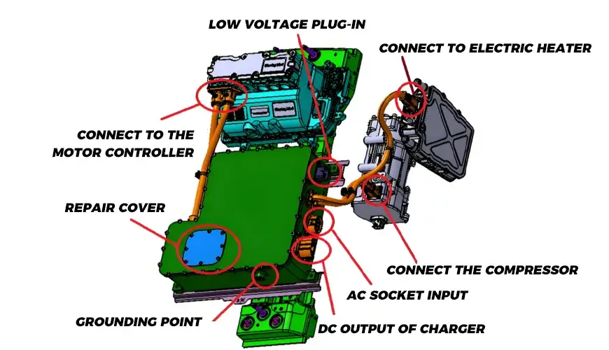
The on-board charger consists of an AC input port, a power unit, a control unit, a low-voltage auxiliary unit, a DC output port and other parts.
AC input port: The AC input port is a connection device between the on-board charger and the ground power supply equipment. When using the on-board charger to charge the electric vehicle, it is recommended to use the typical guidance circuit as a judgment device for the charging interface connection status and the on-board charger input.
Power unit: As the transmission channel of charging energy, the power unit mainly includes electromagnetic interference suppression module, rectifier module, power factor correction module, filter module, full-bridge conversion module and DC output module. Its function is to convert the AC power of the power grid into the high-voltage DC power required by the battery with the cooperation of the control unit.
Control unit: The control unit mainly includes primary side detection and protection module, overcurrent detection and protection module, overvoltage/undervoltage monitoring and protection module, and DSP main control module. Its function is to control the conversion process of the power unit through power electronic switching devices, accurately complete the conversion function through closed-loop control, and provide protection function.
Low-voltage auxiliary unit: The low-voltage auxiliary unit mainly includes CAN communication module, auxiliary power module, and human-computer interaction module. Its function is to provide low-voltage power supply for the power electronic devices of the control unit and realize the connection between the system and the outside world.
DC output port: The DC output port is a connection device between the on-board charger and the battery. The on-board charger output control guide circuit .
Technical Parameters of Electric Vehicle Onboard Charger
The output current can be set according to the voltage of the battery pack of each manufacturer. Under the conditions of rated input voltage and rated load, the efficiency of the on-board charger should be no less than 90%, and the power factor should be no less than 0.92.
Technical parameter error requirements for on-board chargers: The input voltage fluctuation range is ±15% of the rated input voltage; the input voltage frequency fluctuation range is ±2% of the rated frequency; when the on-board charger is operating in the constant voltage output state, the error between its output voltage and the set voltage should be ±1%; when the on-board charger is operating in the constant current output state, the error between its output current and the set current should be ±5%; within the allowable output current range, the period and random deviation of the output current of the on-board charger cannot be greater than 10% of the set current value; when the on-board charger is working in the steady current range, its steady current accuracy should be less than 1%, and when working in the steady voltage range, the steady voltage accuracy should be less than 0.5%.
| No. | Rated Input Voltage/V | Rated Input Current/A | Rated Input Power/kW | Rated Frequency/Hz |
| 1 | Single-phase 220 | 10 | 2.2 | 50 |
| 2 | Single-phase 220 | 16 | 3.5 | 50 |
| 3 | Single-phase 220 | 32 | 7.0 | 50 |
| 4 | Three-phase 380 | 16 | 10.5 | 50 |
| 5 | Three-phase 380 | 32 | 21.0 | 50 |
| 6 | Three-phase 380 | 63 | 41.0 | 50 |
Recommended values of vehicle charger input technical parameters
| Output Voltage Rating | Output Voltage Range | Recommended Nominal Output Voltage |
| 1 | 24-65 | 48 |
| 2 | 55-120 | 72 |
| 3 | 100-250 | 144 |
| 4 | 200-420 | 336 |
| 5 | 300-570 | 384、480 |
| 6 | 400-750 | 640 |
Recommended values of vehicle charger output technical parameters
Electric Vehicle Onboard Charger Charging Interface
The on-board charger of electric vehicles belongs to AC charging, and its interface should meet the requirements of AC charging interface.
During the charging connection process, the protective grounding contact is connected first, and the control confirmation contact and the charging connection confirmation contact are connected last; the disconnection process is the opposite. The electrical connection interface of the vehicle charging interface, and the electrical connection interface of its power supply interface.
The Charging Process of the EV Onboard Charger
1. After the vehicle plug and socket are plugged in, the overall design of the vehicle can automatically activate a certain trigger condition, and put the vehicle in an undriveable state through interlocking or other control measures.
2. The vehicle control device of the electric vehicle determines whether the vehicle plug and the vehicle socket are fully connected by measuring the resistance value between the detection point 3 of the control diagram and PE.
3. After the operator completes the charging start-up settings for the power supply equipment, if the power supply equipment has no faults and the power supply interface is fully connected, S1 is closed, and the power supply control device sends a pulse width modulation (PWM) signal. The electric vehicle vehicle control device determines whether the charging connection device is fully connected by measuring the PWM signal of detection point 2 of the control diagram.
4. After the electric vehicle and the power supply equipment are electrically connected and the on-board charger completes the self-test, the rated charging current value is confirmed by detecting the PWM signal of point 2 in the control diagram; the on-board charger sends a charging induction request signal to the electric vehicle control device, and supplies power to the vehicle control device at the same time or with a delay: the information is confirmed according to the charging protocol. If charging is required, the electric vehicle control device sends a charging message and controls the charging contactor to close, and the on-board charger outputs the required power.
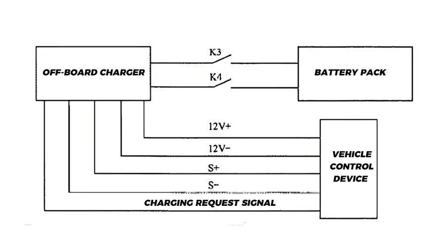
5. The vehicle control device confirms the maximum charging current value that the power supply equipment can currently provide by judging the duty cycle of the PWM signal in the control diagram; the vehicle control device compares the rated input current values of the power supply equipment, the charging connection device and the on-board charger, and sets the minimum value as the current maximum allowable input current of the on-board charger: when it is judged that the charging connection device is fully connected and the maximum allowable input current setting of the on-board charger is completed, K3 and K4 in the control diagram of the vehicle control device are closed, and the on-board charger starts to charge the electric vehicle.
6. During the charging process, the vehicle control device can monitor the voltage value PWM signal duty cycle of the detection point 3 in the control diagram, and the power supply control device can monitor the voltage value of the detection point 1 in the control diagram.
7. During the charging process, when charging is completed or other charging conditions are not met, the vehicle control device sends a charging stop signal to the on-board charger, and the on-board charger stops DC output, CAN communication and low-voltage auxiliary power output.
Conclusion
In essence, the onboard charger is a vital component of the electric vehicle ecosystem. It ensures that your car’s battery gets the power it needs in the right form, efficiently and effectively. Understanding how these chargers work and their role in your EV can help you make more informed decisions about your charging setup. As technology progresses, onboard chargers will continue to evolve, making EV ownership even more convenient and efficient.
Recommended reading: What is an Off-board Charger for Electric Vehicles?

Derek Ke
Hi, I’m Derek Ke, founder of Moreday.com, an expert in solar-protected electrical products and electric vehicle charging.
Over the past 15 years, we have helped nearly 500 customers (such as farms, residential, industrial, and commercial) in 60 countries solve new energy and green power problems. We aim to share more knowledge about solar power generation and new energy with everyone so that green electricity can enter thousands of households.