
Solar
Picking the right MC4 connector cable size isn’t just about which gauge physically fits the crimp — it’s about whether that gauge can safely carry your string’s current over its actual run length without excessive heat or power loss. Our MC4 connector types guide covers which cable diameters fit which connector variant; this guide covers the part that trips up more installs at inspection: the actual MC4 connector cable size calculation, step by step.
Start Here: Which Cable Fits Which Connector
If you just need to know what cable diameter a given MC4 connector variant accepts — standard, fused, diode, T/Y branch — that’s covered in the cable-size table in our MC4 Connector Types guide. This article picks up from there: once you know the connector accepts, say, 4mm² or 10 AWG cable, how do you confirm that’s actually the right size for your specific string?
AWG to mm² Conversion for MC4 Cable
MC4-terminated PV cable is sold in both AWG (common in North America) and mm² (common everywhere else), and the two don’t convert on a clean 1:1 basis. As a practical bridge for the sizes most commonly used with MC4 connectors:
| Metric (mm²) | AWG (approx.) |
|---|---|
| 4 mm² | ≈ 12 AWG |
| 6 mm² | ≈ 10 AWG |
| 10 mm² | ≈ 8 AWG |
Treat these as close equivalents, not exact matches — always confirm against your cable manufacturer’s spec sheet, since actual cross-sectional area varies slightly by manufacturer even within the same nominal AWG or mm² label.
How to Calculate the Right MC4 Connector Cable Size
Cable sizing errors are one of the more common reasons a solar permit set gets kicked back at plan check, and most of them come from skipping one of these steps rather than getting the whole calculation wrong.
Step 1: Calculate the actual circuit current. Use the module’s short-circuit current (Isc), not its rated operating current (Imp) — these differ by roughly 5–10% on most crystalline modules, and starting from the wrong number compounds every step after it.
Step 2: Apply the NEC 690.8 safety factor — twice. In the US, NEC 690.8 requires a 1.25× multiplier applied in two separate places: once to establish the maximum circuit current from Isc, and again to establish the required conductor ampacity from that figure. Applying the factor only once — a common shortcut — under-sizes the cable relative to code, even though the arithmetic “looks” done.
Step 3: Check ampacity against the correct temperature column. NEC 690.31(C) requires 90°C-rated conductors for PV source circuits, so the sizing check needs to come from the 90°C column of NEC Table 310.16 — not the 60°C column, which is a frequent error and can leave real safety margin unaccounted for once a rooftop conduit reaches its actual operating temperature.
Step 4: Apply temperature and bundling derating. A rooftop conduit in direct sun can reach 60–70°C even in a moderate climate, well above the 30°C ambient most base ampacity tables assume — this alone can cut a conductor’s usable ampacity by 40–50%. Running multiple circuits in the same conduit adds further derating on top of that.
Step 5: Check voltage drop, and use whichever result gives the larger cable. Even a conductor with adequate ampacity can still lose more than the accepted 2% DC voltage drop target over a long run. Conductor resistance is commonly published per 1,000 feet (a common way wire tables list DC resistance), so the formula needs that unit built in: voltage drop (V) = current (A) × resistance (Ω per 1,000 ft) × [2 × one-way length (ft)] ÷ 1,000. If you’re working from a resistance value already given in ohms per foot instead, drop the ÷1,000 term. If the ampacity-driven size and the voltage-drop-driven size disagree, install the larger of the two.
A Worked Example
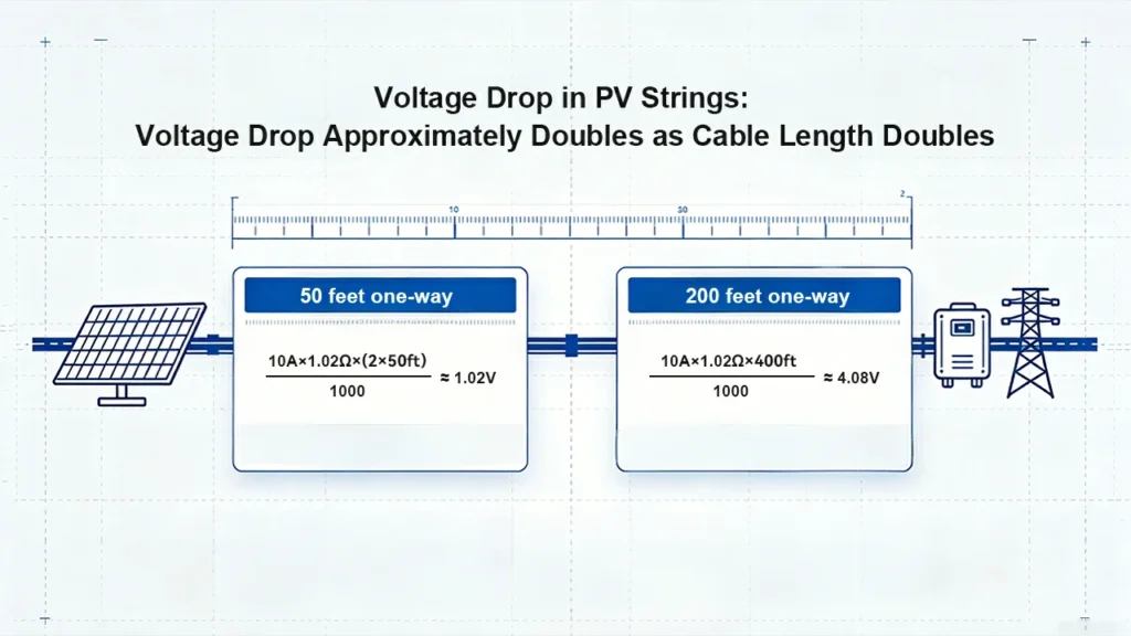
A string with a 10A Isc, run 50 feet one-way, using 10 AWG copper PV wire (approximately 1.02 Ω per 1,000 ft): voltage drop = 10A × 1.02 Ω/1,000ft × (2 × 50ft) ÷ 1,000 = 10 × 1.02 × 100 ÷ 1,000 ≈ 1.02V. On a string operating around 400V, that’s roughly 0.25% — comfortably under the 2% target. The same current over a 200-foot run on the same gauge: 10 × 1.02 × 400 ÷ 1,000 ≈ 4.08V — exactly four times the drop, since doubling the one-way length to 200ft (4× the original 50ft) scales voltage drop linearly. This is the point where most installers find they need to step up an MC4 connector cable size purely for voltage drop, even though ampacity alone wouldn’t have required it.
Why the Right MC4 Connector Cable Size Depends on Run Length, Not Just Current
It’s tempting to treat MC4 connector cable size as a lookup: “this current needs this gauge.” That works for ampacity, but voltage drop scales with distance, not just current — which is why the same 10A string might be perfectly fine on 10 AWG at 50 feet and need to move up to 8 AWG or larger once the run stretches past 150–200 feet, purely to keep losses under the 2% target. Rooftop layouts with a long conduit run back to a ground-mounted inverter, or utility-scale arrays with long home-runs to a combiner box, are the cases where this shows up most often — the connector and crimp are identical either way, but the correct cable size on paper is not.
Common MC4 Connector Cable Size Mistakes
Sizing to Imp instead of Isc — starts the whole calculation from a current figure that’s already too low.
Applying the NEC 690.8 multiplier once instead of twice — under-sizes the required ampacity relative to code.
Reading ampacity from the 60°C column — PV source circuits require the 90°C column per NEC 690.31(C); using the wrong column overstates how much margin you actually have.
Ignoring rooftop temperature and conduit bundling — base ampacity tables assume a mild ambient that a dark rooftop conduit routinely exceeds.
Using total circuit length instead of one-way distance — the standard voltage-drop formula already accounts for the return path with its factor of 2; doubling the length again under-sizes the cable.
Terminating an undersized cable into an MC4 connector anyway because “it fits the crimp” — physical fit inside the connector’s gland range doesn’t mean the cable is rated for the circuit’s actual current and length. Always confirm the calculation before confirming the connector.
Does This Apply Outside North America?
The specific code references above (NEC 690.8, 690.31(C), 310.16) are US-specific, but the underlying methodology — calculate real current, apply a safety margin, check ampacity at the correct temperature rating, then check voltage drop and take the larger result — is the same approach used under IEC 60364 and other international wiring codes, just with different reference tables and derating factors. If you’re sizing cable for an MC4 connector outside the US, use the same five-step sequence above and substitute your local code’s ampacity tables and safety margins for the NEC figures.
FAQ
Source: NEC 690.8, 690.31(C), and 310.16 sizing methodology, cross-referenced against PhotovoltaicCable.com’s NEC 690.8 cable sizing guidance.
Related reading: MC4 Connector: The Complete Guide to Solar PV Connections · MC4 Connector Types: The Complete 2026 Comparison Guide · How to Crimp MC4 Connectors · DC Arc Faults in Solar Systems